Transformer-isolated flyback converters and methods for regulating output current thereof

a technology of transformers and converters, applied in the direction of electric variable regulation, process and machine control, instruments, etc., can solve the problems of reducing reliability and long-term stability, affecting the circuit of fig. 1 and the cost and size of power converters are significan

Inactive Publication Date: 2007-05-31
MICROCHIP TECH INC
View PDF7 Cites 79 Cited by
  • Summary
  • Abstract
  • Description
  • Claims
  • Application Information

AI Technical Summary

Problems solved by technology

The feedback circuit typically raises the cost and size of a power converter significantly and also lowers reliability and long-term stability, as opto-couplers change characteristics with age.
However, the circuit of FIG. 1 suffers some serious drawbacks.
Firstly, the output current of this circuit is affected by variation in control circuit and load characteristics that are difficult to account for.
Secondly, a constant-power converter must be tailored to a specific load and cannot be used as a universal constant current source.
Indeed, the open-circuit output voltage and the short-circuit output current become uncontrollably high with the circuit of FIG. 1.

Method used


Image

  • Transformer-isolated flyback converters and methods for regulating output current thereof
  • Transformer-isolated flyback converters and methods for regulating output current thereof
  • Transformer-isolated flyback converters and methods for regulating output current thereof

Examples


Embodiment Construction

[0018] The present invention provides novel circuits and methods for controlling output current of a switching power supply. As a result, accuracy of a switching power converter can be improved and reduction in the component count can be achieved by incorporating one or more aspects of the present invention. The present invention includes, alone or in combination, a unique oscillator circuit whose switching frequency is independent of the timing and power component variation and adaptive to varying output load.

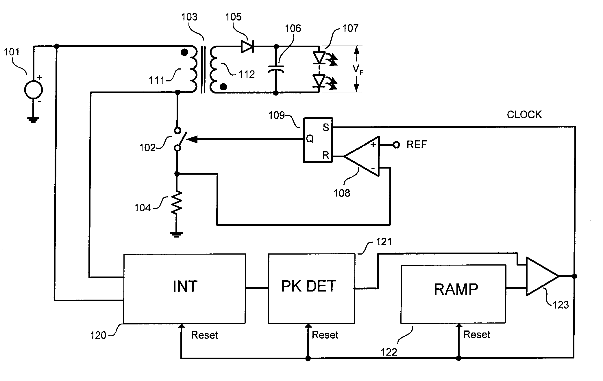
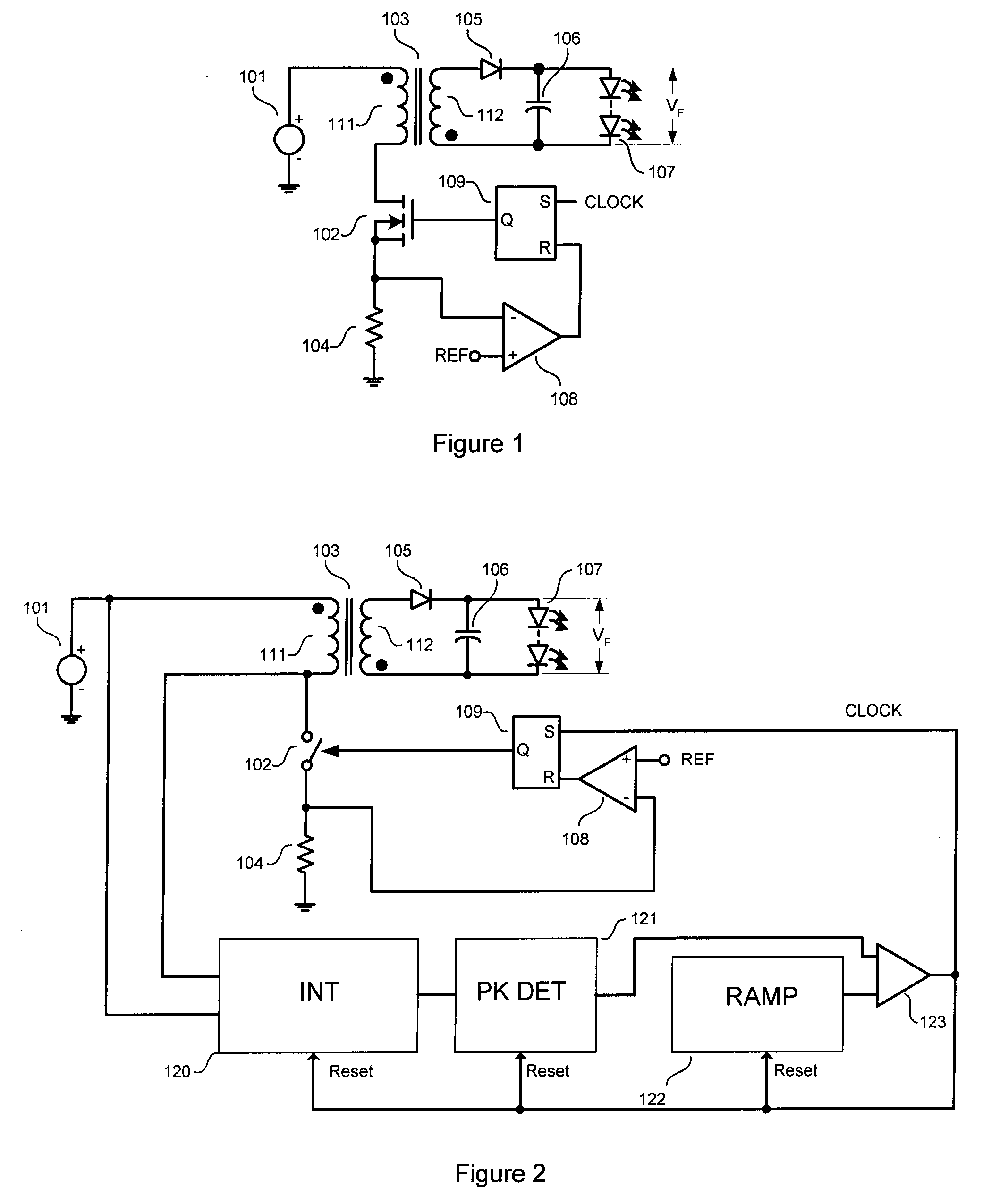
[0019]FIG. 2 shows a simplified block diagram of the first embodiment of the present invention. The depicted circuit is a flyback converter delivering constant power output to an output LED load. The circuit includes an input voltage source 101, a flyback transformer 103 having a primary winding 111 and a secondary winding 112, a secondary rectifier diode 105, a smoothing capacitor 106, a controlled power switch 102, a current sense resistor 104, a comparator 108, a flip-flop...


PUM


Abstract

A system and method for delivering regulated power and current to an output load has a flyback transformer having a primary winding and a secondary winding. The secondary winding delivers stored energy to the output load. An oscillator circuit is provided for generating a periodical signal. A switching circuit is coupled to the flyback transformer and the oscillator circuit for energizing the primary winding to a reference current level each cycle of the oscillator circuit. The oscillator circuit has an integrator for deriving a time integral of a voltage at the primary winding. The oscillator circuit has a peak detector coupled to the integrator for holding a peak value of the time integral. The oscillator circuit further has a ramp generator for producing a ramp signal. A comparator is provided for comparing the peak value with the ramp signal and generating the periodical signal whenever the ramp signal exceeds the peak value.

Description

RELATED APPLICATION [0001] This application is related to U.S. Provisional Application Ser. No. 60 / 740,135, filed Nov. 28, 2005, and entitled, “TRANSFORMER-ISOLATED FLYBACK CONVERTERS AND METHODS FOR REGULATING OUTPUT CURRENT THEREOF”. The present patent application claims the benefit under 35 U.S.C. §119(e).FIELD OF THE INVENTION [0002] The present invention relates generally to power supplies, and, more specifically, to switching power converters including an isolation power transformer of the flyback type, and even more specifically to a method and apparatus for controlling output current of a switching power converter by monitoring voltage at the primary winding of the transformer. BACKGROUND OF THE INVENTION [0003] Electronic devices typically incorporate low voltage DC power supplies to operate internal circuitry by providing a constant output voltage or current from a wide variety of input sources. Switching power converters are in common use to provide a voltage-regulated so...

Claims


Application Information

Patent Timeline
Patent Type & Authority Applications(United States)
IPC IPC(8): H02M3/335
CPCH02M3/33523
Inventor MEDNIK, ALEXANDERTIRUMALA, ROHITTAO, ZHIBO
Owner MICROCHIP TECH INC
Why Eureka
Try Eureka