Capacitor microphone and diaphragm therefor

a capacitor microphone and diaphragm technology, applied in the field of capacitor microphones, can solve the problems of difficult elimination of tensile stress, degrade the vibration characteristics and sensitivity of the capacitor microphone, and the vibration characteristics may greatly alter in response, so as to improve the save electricity, and improve the effect of vibration characteristics and sensitivity

Inactive Publication Date: 2007-05-31
YAMAHA CORP
View PDF4 Cites 44 Cited by
  • Summary
  • Abstract
  • Description
  • Claims
  • Application Information

AI Technical Summary

Benefits of technology

[0017] It is an object of the present invention to provide a capacitor microphone having a diaphragm, in which tensile stress is eliminated so as to improve vibration characteri...

Problems solved by technology

In the capacitor microphone in which the diaphragm is attached to the substrate via a plurality of springs, it may be possible to reduce tensile stress applied to the diaphragm by way of elasticity of springs; however, it is very difficult to eliminate tensile stress.
This degrades vibration characteristics and sensitivity of the capacitor microphone.
However, since the diaphragm is composed of the thermoplastic resin film having a relatively high thermal expansion coefficient, there is a possibility that vibration characteristics may greatly alter in response to temperature variations.
In addition, it is difficult to produce the diaphragm having the corrugated portions with a required precision.
This makes it difficult to downsize the diaphragm an...

Method used


Image

  • Capacitor microphone and diaphragm therefor
  • Capacitor microphone and diaphragm therefor
  • Capacitor microphone and diaphragm therefor

Examples


first embodiment

1. First Embodiment

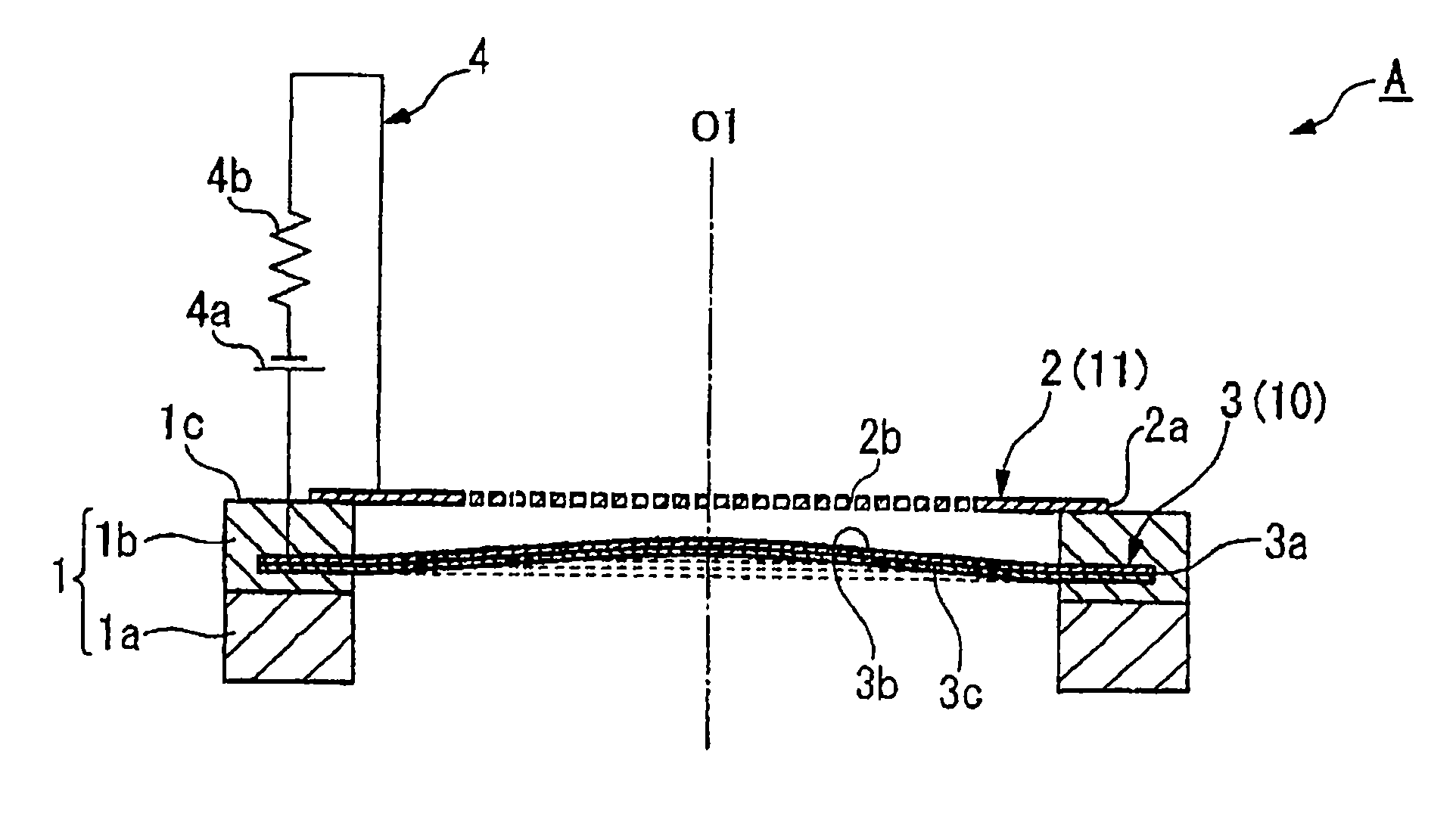
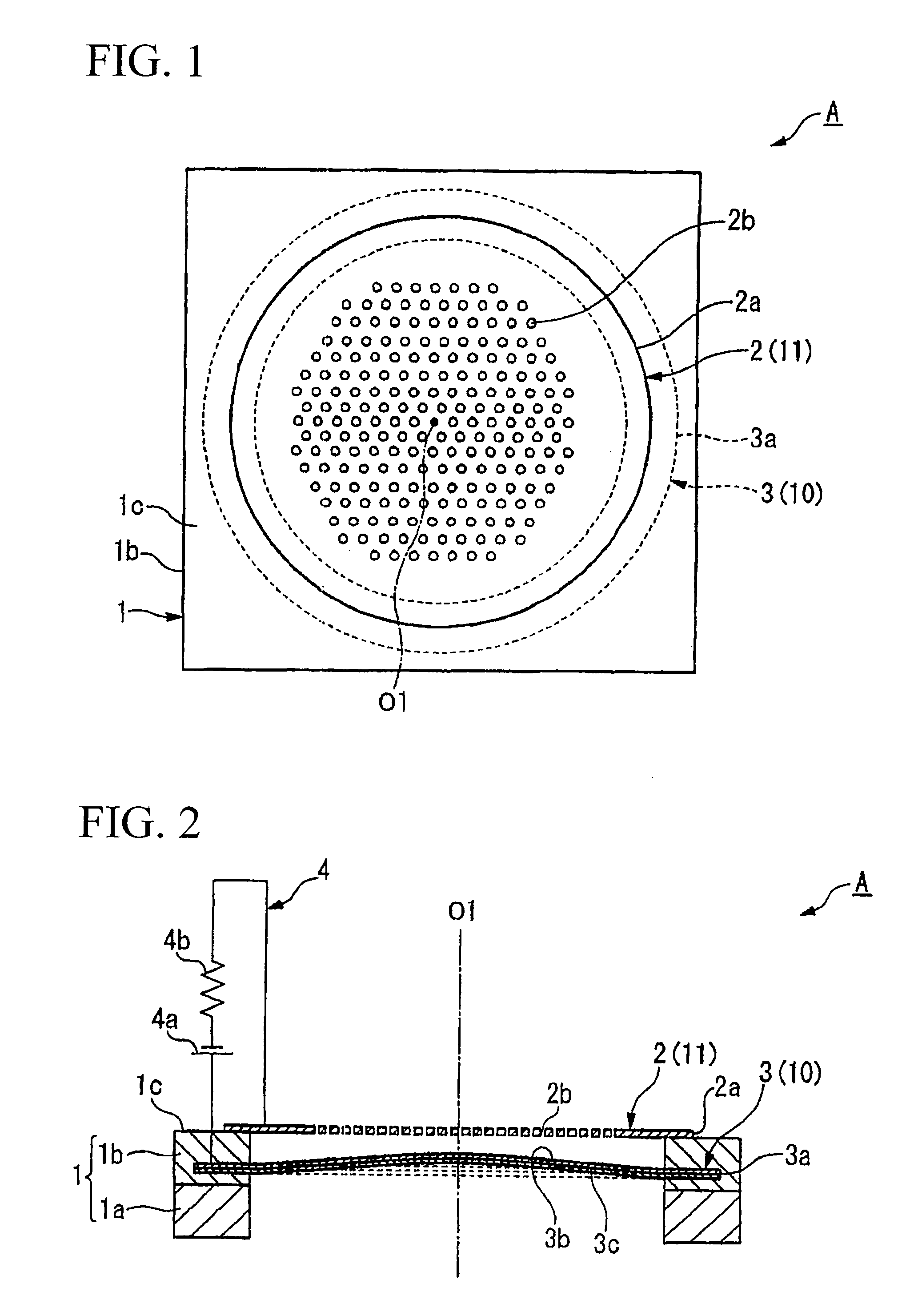
[0130] As shown in FIGS. 1 and 2, a capacitor microphone A of a first embodiment of the present invention includes a ring-shaped support 1, which has circular inner holes and which is formed by laminating a monocrystal silicon substrate 1a and an oxide film 1b, a back plate (or a fixed electrode) 2, which is formed approximately in a circular shape and is supported by an upper end 1c of the support 1, and a diaphragm 3, which is positioned substantially in parallel with the back plate 2 in proximity to the inner holes of the support 1 and which has an outer circumferential end 3a that is supported and embedded in the oxide film 1b. The capacitor microphone A is equipped with a bias voltage applying device 4 in which one end is connected to the back plate 2 and the other end is connected to the diaphragm 3. The bias voltage applying device 4 includes a bias voltage source 4a and a resistor 4b, which are connected in series.

[0131] The support 1 is formed by laminat...

second embodiment

2. Second Embodiment

[0161]FIG. 14A is a cross-sectional view showing the constitution of a capacitor microphone 1001 in accordance with a second embodiment of the present invention. The capacitor microphone 1001 includes a sound sensing portion and a detection portion, which are shown in FIG. 14A.

[0162] (a) Constitution of Sound Sensing Portion

[0163] The sound sensing portion of the capacitor microphone 1001 includes a back plate 1010 and a diaphragm 1030 (see FIG. 14B), which are connected to a spacer 1044 at prescribed ends thereof. That is, the back plate 1010 and the diaphragm 1030 are supported in parallel with each other via the spacer 1044, by which a pressure chamber (or an air gap) 1046 is formed therebetween. The back plate 1010 is positioned relative to the diaphragm 1030, which is connected to the circuitry for sensing sound. The back plate 1010 has a plurality of sound holes 1018, i.e., a plurality of through holes allowing sound waves to propagate therethrough toward...

third embodiment

3. Third Embodiment

[0205]FIG. 23 is a cross-sectional view showing the constitution of a capacitor microphone 2001 in accordance with a third embodiment of the present invention, which is a silicon microphone that is produced by way of semiconductor manufacturing processes. The capacitor microphone 2001 includes a sound sensing portion and a detection portion.

[0206] (a) Constitution of Sound Sensing Portion

[0207] The sound sensing portion of the capacitor microphone 2001 includes a diaphragm 2010, a back plate 2030, and a support 2040. The diaphragm 2010 and the back plate 2030 are supported by the support 2040 with an air gap 2050 therebetween. The back plate 2030 has a plurality of through holes 2032. The support 2040 has an opening 2042, which is combined with the diaphragm 2010 so as to form a back cavity. It is possible to rearrange the diaphragm 2010 to be close to a sound source rather than the back plate 2030.

[0208] The diaphragm 2010 includes non-fixed portions correspon...


PUM


Abstract

In a capacitor microphone, a diaphragm is positioned opposite to a fixed electrode for covering inner holes of a ring-shaped support, wherein when the diaphragm is deflected to approach the fixed electrode due to electrostatic attraction upon application of a bias voltage, internal stress that occurs on the diaphragm is canceled by compressive stress that is applied to the diaphragm in advance. The diaphragm is formed using a multilayered structure including a first thin film and a second thin film whose internal stress differs from the internal stress of the first thin film, thus adjusting the total internal stress thereof. The diaphragm can be formed in such a way that a center layer having a single-layered structure is sandwiched between first and second coating layers having controlled residual tensions and resistance against hydrofluoric acid.

Description

BACKGROUND OF THE INVENTION [0001] 1. Field of the Invention [0002] The present invention relates to capacitor microphones using diaphragms, which are produced by way of manufacturing processes of semiconductor devices. The present invention also relates to diaphragms and manufacturing methods of diaphragms. [0003] This application claims priority on five Japanese patent applications, i.e., Japanese Patent Application No. 2006-89680, Japanese Patent Application No. 2005-277377, Japanese Patent Application No. 2006-28439, Japanese Patent Application No. 2006-94414, and Japanese Patent Application No. 2006-224978, the contents of which are incorporated herein by reference. [0004] 2. Description of the Related Art [0005] Conventionally, a variety of capacitor microphones have been produced by way of manufacturing processes of semiconductor devices. For example, Japanese Patent Application Publication No. 2004-506394 and U.S. Pat. No. 5,452,268 teach examples of capacitor microphones. T...

Claims


Application Information

Patent Timeline
IPC IPC(8): H04R25/00
CPCB81B3/0072B81B2201/0257B81B2203/0127H04R19/005
Inventor SUZUKI, YUKITOSHIHIRADE, SEIJISUZUKI, TAMITOSAKAKIBARA, SHINGOTERADA, TAKAHIRO
Owner YAMAHA CORP
Why Eureka
Try Eureka