
Photochromic Lens

a technology of photochromic dyes and lenses, applied in the field of photochromic lenses, can solve the problems of fatigue or wear, the plastic resin used in the manufacture of ophthalmic lenses does not provide the best host material for photochromes, and the photochromic dyes cannot be easily activated, so as to reduce the amount of photochromic dyes, good resistance to photochromic dye fatigue, and high impact resistance

Active Publication Date: 2007-05-31
HOYA OPTICAL LABS OF AMERICA INC +1
View PDF65 Cites 55 Cited by
  • Summary
  • Abstract
  • Description
  • Claims
  • Application Information

AI Technical Summary

Benefits of technology

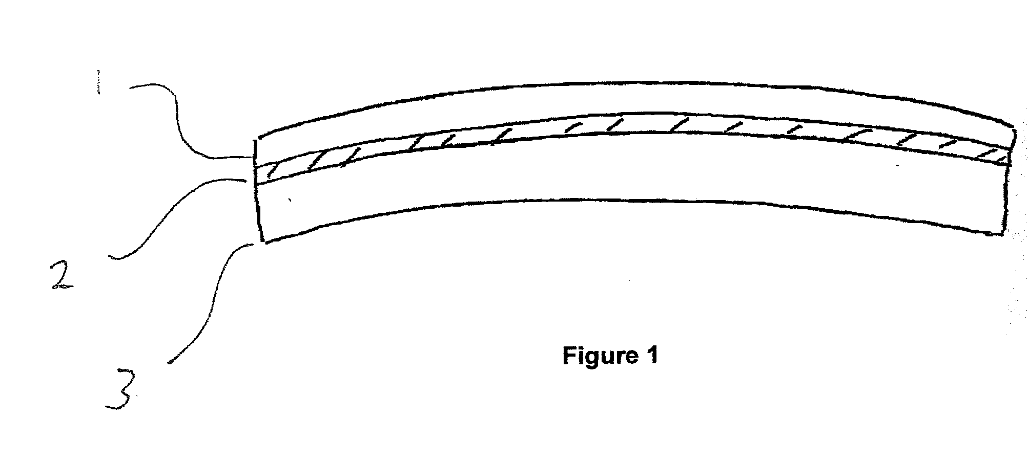
[0015] It is an object of the present invention to provide a photochromic lens that includes a relatively long service life and provides good resistance to photochromic dye fatigue. It is another object of the present invention to provide a photochromic lens that reduces the amount of photochromic dyes used during the manufacturing process. It is yet another embodiment of the present invention to provide a photochromic lens that is not limited from use with surface designs, such as bi-focal lenses.
[0016] It is yet another object of the present invention to provide a method of manufacturing a photochromic lens that can utilize most commercially available cast resins, such as those made by thermoset or radiation initiated processes. It is yet another embodiment of the present invention to provide a photochromic lens having high impact resistance, using known and commercially available high impact resinous layers and materials, such as polycarbonate.

Problems solved by technology

It was recognized early on that the plastic resins used to make ophthalmic lenses do not provide the best host material for photochromes.
In such plastic resin materials, the photochromes do not activate easily and fatigue or wear-out in a short period of time.
This is one of the limitations to putting photochromes into polymeric host materials that are used to form the bulk of the lens.
As is described in the '758 patent, one of the drawbacks of incorporating photochromes directly into the polymeric host material is the problem of fatigue or light fatigue.
Photochromes are believed to lose their ability to change color specifically resulting from the irreversible decomposition of the photochromic compound, which occurs due to repeated exposure to UV light over time.
A major limitation of the photochromic coating approach is the poor scratch resistance of such a coating even with another hard coating on top of the photochromic coating.
Additionally, if the photochromic coating is scratched, it will result in streaks of areas on the lens that do not activate.
One problem with these approaches is that the mechanical stability of the composite is not very durable in subsequent processing to make the ophthalmic lens and mount it into a frame.
Processes such as surfacing the lens to prescription power and edge cutting to fit into a frame result in chipping of the composite due to the different cutting and grinding characteristics of the materials.
Drilling of the composite to mount into rimless frames also results in chipping of the composite.
Additionally, if such a lens is a semi-finished product and requires further processing (e.g., grinding, polishing, etc), it is clear that photochromes present in the base lens will be ground and / or polished away, inevitably diminishing the desired coloring effects of the finished lens product.
However, a coating of this thickness is not well suited for application on the surface of a segmented, multi-focal lens because it is too thick.
Typically, a coating of this thickness creates such problems as the creation of an unacceptable segment line, as well as coating thickness uniformity issues around the segment line.
Problems that have been raised particularly regarding use of photochromic laminates or inserts in injection molding process include, primarily, the bleeding of the functional layer (e.g., photochromic layer) material of the laminate or wafer.
Often bleeding occurs due to the deformation of the photochromic layer under the high temperature and pressure used during the injection molding process.
This is thought to occur due to either an excess amount of functional layer material and / or inadequate softening properties of the functional layer material.
Further, this bleeding can interfere with any additional coating layers that are applied to the lens after injection-molding.
However, the issues addressed by Bhalakia do not include providing a laminate or insert that may be used in a cast-lens manufacturing process.

Method used


Image

  • Photochromic Lens
  • Photochromic Lens

Examples


example 1

[0035] A photochromic film was prepared according to the examples in U.S. patent application Ser. No. 10 / 938,275. The polyurethane layer is 40 μm thick, and the protective layers are 76 μm cellulose acetate butyrate (CAB) films (K-Mac). The polyurethane layer and protective layers were bonded together to form a photochromic laminate. The laminate was masked with a 3M film (24S56W). A 70-mm disk was die-cut off from the above laminate, and formed into a 6-base laminate wafer through a thermo-vacuum forming process. The temperature was 255° F., and the forming time was 200 seconds. A 70-mm lens cast gasket and two 6-base glass molds (front and back) were used to cast the photochromic lens. The masked film is thereafter removed prior to placement of the laminate wafer into the gasket. The laminate wafer was fixed in the gasket about 1 mm away from the front mold surface with help of a spacer. A clear UV-curable cast resin from OptiCast was injected into the front and back cavities. The...

example 2

[0036] To a solution of 18% by weight of a polyester urethane (Tecoflex CLC-93A from Thermedics) in THF solvent was added 2% each of Tinuvins 765,144, and Irganox 1010 (all from CIBA Corporation), and 0.8% of naphthopyran photochromic dye VP0762 (Proprietary Vision-Ease Dye). The mixture was then cast on a flat borosilicate glass plate and the solvent allowed to evaporate. A photochromic film of about 0.2 mm thick was obtained. The photochromic film was then placed between two glass molds held together with a standard casting gasket. A mixture of 58.3 grams of casting monomer P11 (NOF Corporation), 0.6 gram of Tinuvin 765, 0.26 gram of Trigonox 23 catalyst and 0.37 gram of Trigonox 21 catalyst was introduced between the glass molds and around the polyurethane film. The mold and gasket assembly was placed in a water bath and cured in a cycle that ramps the lens up to 90° C. over a 20 hour period. The resultant thermoset, cast lens is then separated from the glass molds. The lens had ...

example 3

[0037] A photochromic film was prepared according to the examples in U.S. patent application Ser. No. 10 / 938,275. The polyurethane layer is 40 μm thick, and the protective layers are 350 μm thick polycarbonate films. The polyurethane layer and protective layers were bonded together to form a photochromic laminate. The laminate was masked with a 3M film (24S56W). A 70-mm disk was die-cut off from the above laminate, and formed into a 6-base laminate wafer through a thermo-vacuum forming process. The temperature was 255° F., and the forming time was 200 seconds. A 70-lens cast gasket and two 6-base glass molds (front and back) were used to cast the photochromic lens. The masked film is thereafter removed prior to placement of the laminate wafer into the gasket. The laminate wafer was placed against the front mold surface and placed into the gasket with the back mold. A clear UV-curable cast resin from OptiCast (OPIV-B) was injected into the back cavity. The cast resin in the above set...


PUM

PropertyMeasurementUnit
Temperatureaaaaaaaaaa
Lengthaaaaaaaaaa

Abstract

A cast photochromic lens including a photochromic film and a cast resin, curable by heat or radiation.

Description

CROSS REFERENCE TO RELATED APPLICATIONS [0001] This application claims the benefit of priority from U.S. Provisional Application No. 60 / 722,848 filed on Sep. 29, 2005 entitled Photochromic Lens; and is a Continuation-In-Part of U.S. application Ser. No. 10 / 938,275 filed on Sep. 9, 2004 entitled Photochromic Polyurethane Laminate, which claims the benefit of priority from U.S. Provisional Application Ser. No. 60 / 501,819 filed Sep. 9, 2003 entitled Photochromic Film and Method of Manufacture, and which claims the benefit of priority from U.S. Provisional Application Ser. No. 60 / 501,820 filed on Sep. 9, 2003 entitled Photochromic Laminate which are hereby incorporated herein by reference.BACKGROUND OF THE INVENTION [0002] Many methods and devices are known in the art for incorporating photochromic characteristics into an ophthalmic lens. One example of a method known in the art includes imbibing or infusing photochromes into the host material or base lens from a transfer layer (that is...

Claims


Application Information

Patent Timeline
IPC IPC(8): B32B27/36B32B27/40
CPCB32B27/08Y10T428/269B32B27/40C08G18/10C08G18/4277C08G18/758C08K5/0041C08L75/04G02B1/041B32B27/18B29D11/0073C08G18/3206C08L2666/20Y10T428/31507Y10T428/31551Y10T428/31576
Inventor QIN, XUZHISUGIMURA, HIDEYOBOULINEAU, MICHAEL S.MORAVEC, THOMAS J.HARRIS, DEREK
Owner HOYA OPTICAL LABS OF AMERICA INC
Learn More