Exercise treadmill for pulling and dragging action

Inactive Publication Date: 2007-05-31
ELLIS JOSEPH K
View PDF3 Cites 73 Cited by
  • Summary
  • Abstract
  • Description
  • Claims
  • Application Information

AI Technical Summary

Benefits of technology

[0021] Generally speaking, the internal mechanical components of the treadmill are similar to (or can be similar to or the same as) the internal mechanical components of known treadmills. The treadmill comprises an endless belt looped about rollers or pulleys so as to provide a platform on which the user can stand, walk and/or run. A deck below a por...

Problems solved by technology

However, the inventor is unaware of any specific exercise treadmill that is structured to allow the user to com...

Method used


Image

  • Exercise treadmill for pulling and dragging action
  • Exercise treadmill for pulling and dragging action
  • Exercise treadmill for pulling and dragging action

Examples


Embodiment Construction

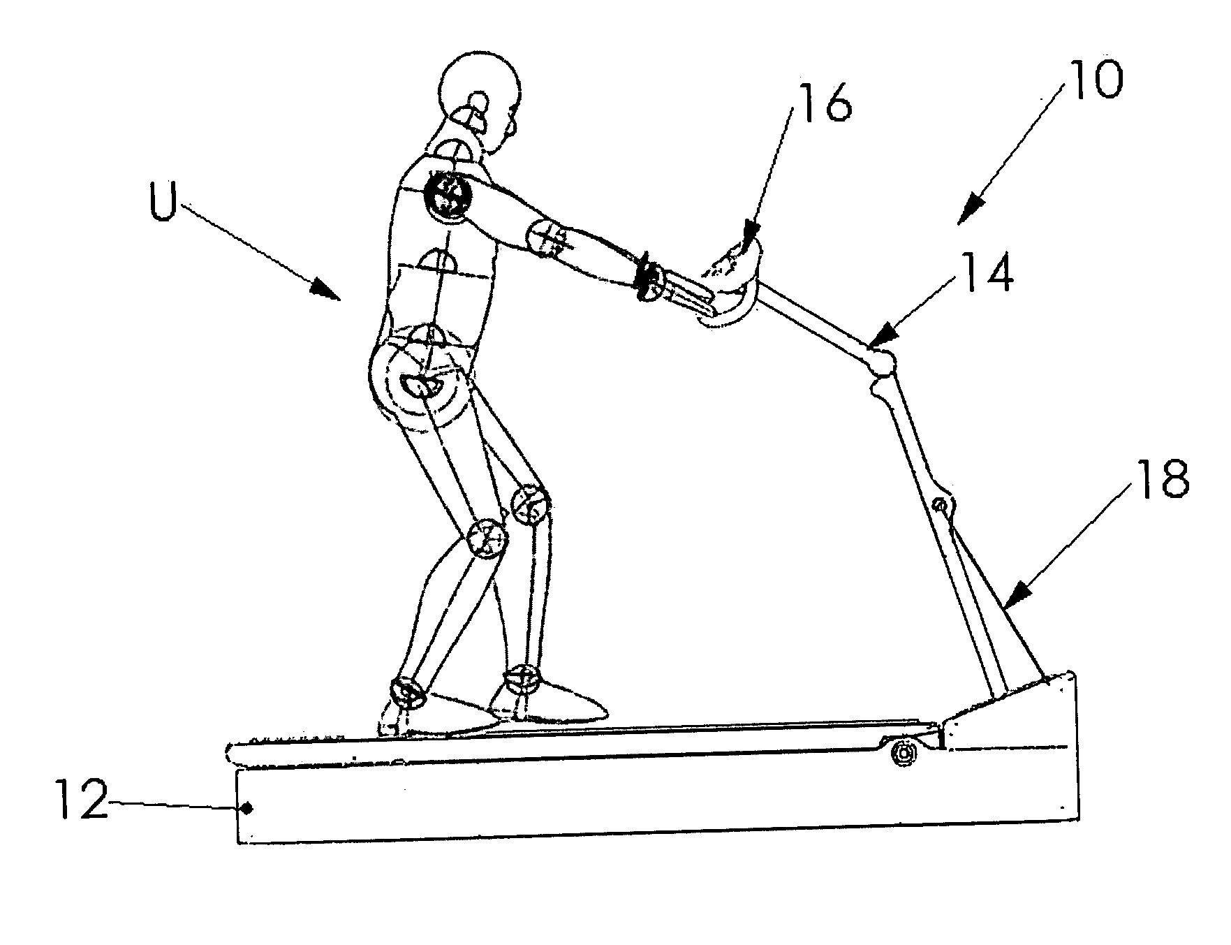
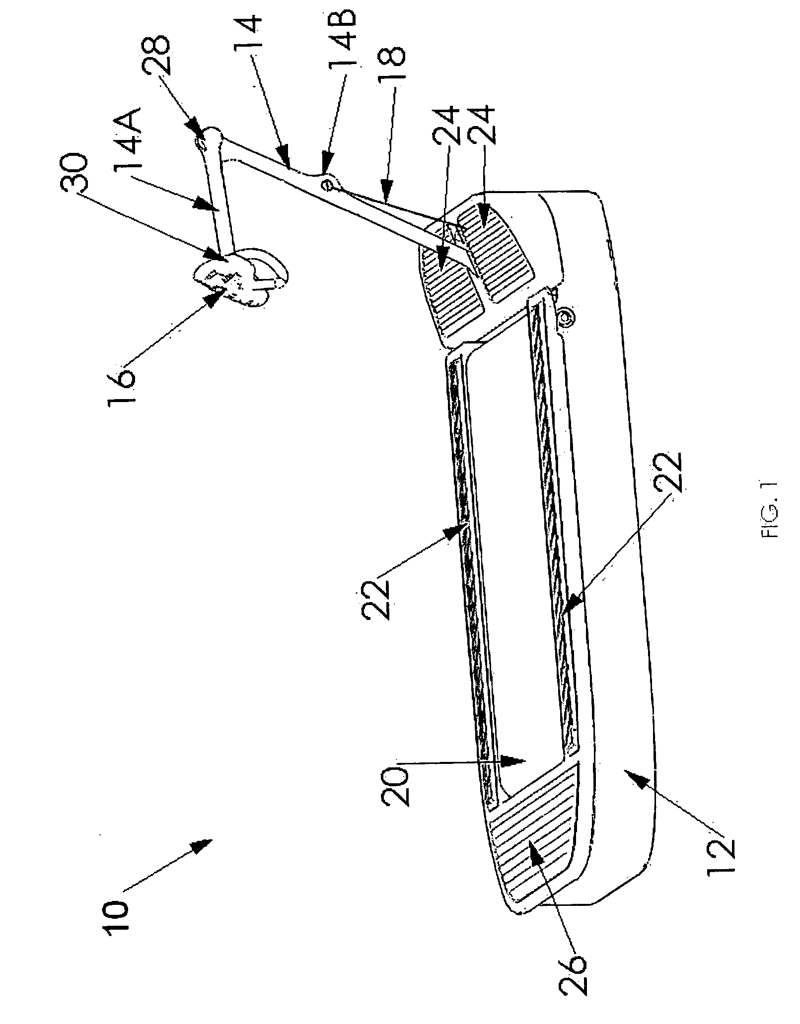
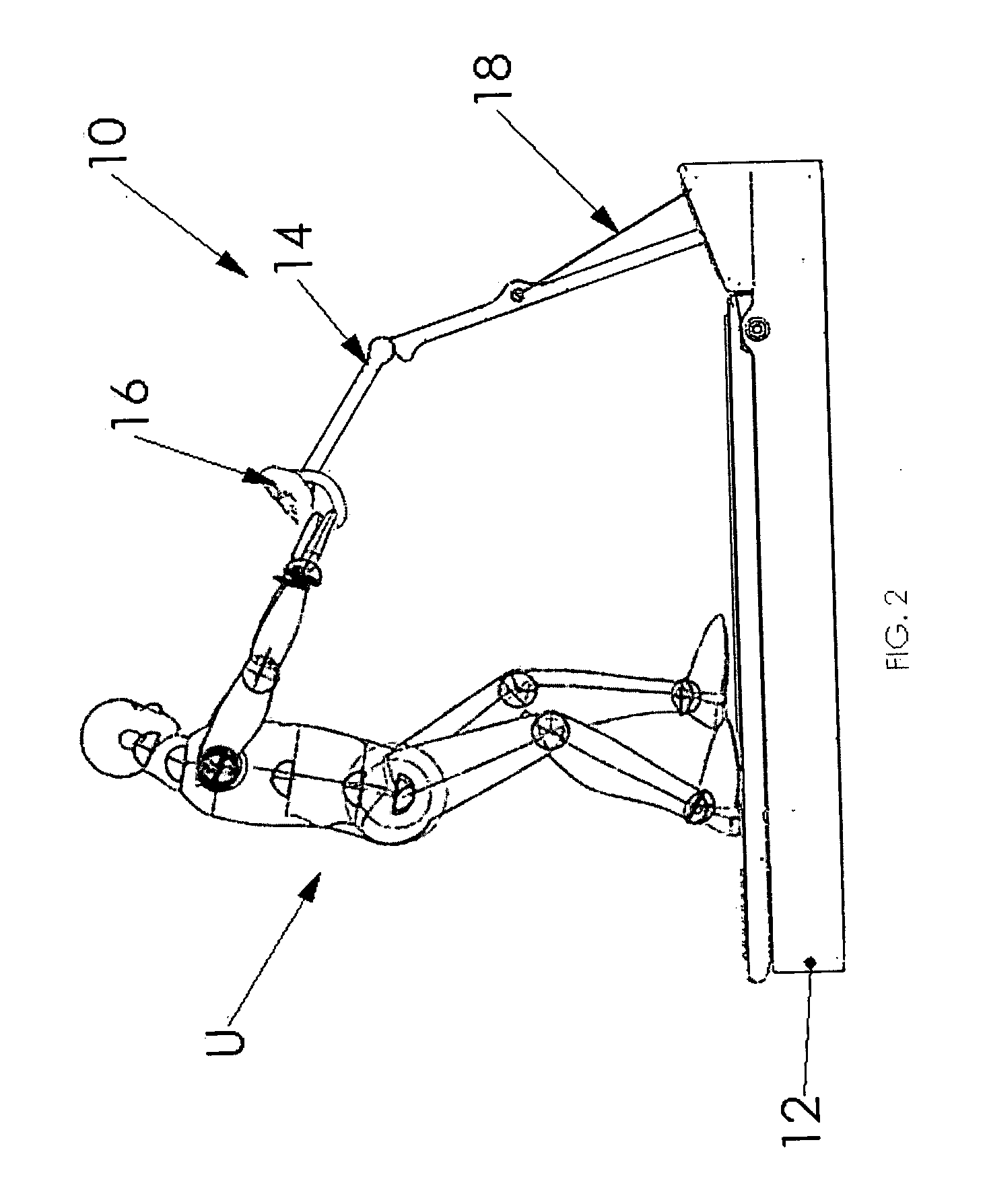
[0057] Referring now to the appended figures, the invention will be described in connection with representative preferred embodiments. FIG. 1 is a perspective view of the invention illustrating the relationship between the various major components of the device. FIG. 2 is a side view of the invention showing a user operating the invention in a flat or level dragging or pulling simulation. FIG. 3 is a side view of the invention showing a user operating the invention in an inclined dragging or pulling simulation. FIG. 4 is a side sectional view of the invention showing a schematic of the internal mechanical components of the invention.

[0058]FIGS. 4A through 4F show several illustrative weight resistance means suitable for use with the invention. FIG. 4A is a side schematic of a spring-based weight resistance means suitable for the invention, such as a spring with a known spring constant in tension. FIG. 4B is a side schematic of a compression spring-based weight resistance means suit...


PUM


Abstract

An exercise treadmill of the type having an endless moveable surface looped around rollers or pulleys to form an upper run and a lower run, the movable surface being rotated when one of the rollers or pulleys is rotated, an exercise surface on for walking or running while exercising, and a weight resistance means for simulating the dragging or pulling of a load, wherein the endless movable surface moves in a direction simulating walking or running backwards.

Description

CROSS REFERENCE TO RELATED APPLICATIONS [0001] This patent application is a continuation-in-part of U.S. patent application Ser. No. 11 / 289,916 having a filing date of 30 Nov. 2005 entitled Exercise Treadmill For Pulling And Dragging Action, which is incorporated herein in its entirety by this reference.BACKGROUND OF THE INVENTION [0002] 1. Technical Field [0003] This invention relates to the general technical field of exercise, physical fitness and physical therapy equipment and machines and to the more specific novel technical field of a mechanically, electrically and electronically operated reverse treadmill machine designed to simulate a dragging or pulling motion when operated by the user. [0004] 2. Prior Art [0005] Exercise, physical fitness and physical therapy equipment and machines are available in various configurations and for various purposes, and are available for all of the major muscle groups. The majority of such equipment and machines, especially in the exercise fie...

Claims


Application Information

Patent Timeline
IPC IPC(8): A63B22/02
CPCA63B21/0618A63B21/154A63B22/0023A63B22/02A63B22/0235A63B22/0242A63B22/0285A63B23/047A63B24/00A63B2022/0278A63B2230/06
Inventor ELLIS, JOSEPH K.
Owner ELLIS JOSEPH K
Why Eureka
Try Eureka