
Bone fixation device and method

a bone fixation device and bone technology, applied in the field of bone fixation devices, can solve the problems of short lateral malleolus oblique fracture, difficult to achieve stable fixation of two bone segments having an oblique contact surface, and easy so as to avoid further shortening of two bone fragments and facilitate healing

Active Publication Date: 2007-05-31
MEDOFF ROBERT J +2
View PDF25 Cites 83 Cited by
  • Summary
  • Abstract
  • Description
  • Claims
  • Application Information

AI Technical Summary

Benefits of technology

[0014] An object of the invention is to provide a method and apparatus for fixation of a fracture using an implant that produces compressive load (oblique or perpendicular) to the long axis of the implant across an oblique fracture line in order to facilitate healing and avoid further shortening of the two bone fragments.
[0015] A further object of the invention is to provide such fixation in which a counter-rotational torque is generated to prevent sliding of the fragments and production of a destabilizing force couple.
[0016] A further object of the invention is to provide a device that is simple to apply, reduces the risk of iatrogenic comminution from screw holes near the fracture site, allows improved resistance to rotational torque, and avoids shortening at the fracture site.

Problems solved by technology

Achieving stable fixation of two bone segments having an oblique contact surface can be difficult.
For example, external rotation injuries of the ankle may often result in a short oblique fracture of the lateral malleolus.
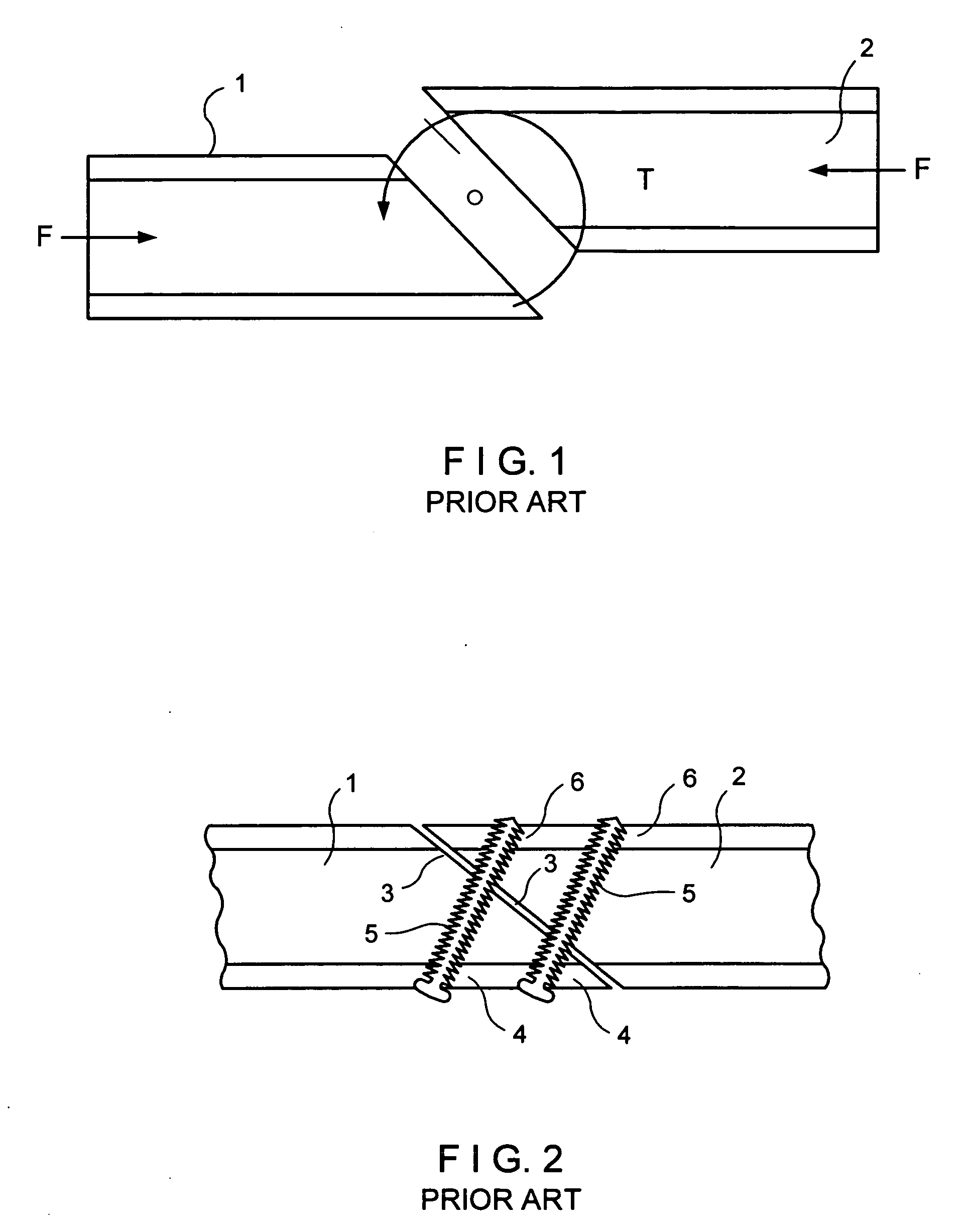
Because of the oblique orientation of the fracture line, simple apposition of the bone surfaces is nearly always unstable, since axial loading forces on the bone cause sliding of the two bone surfaces along the oblique fracture line and contribute to potential problems of shortening, non-union, and loss of reduction.
For fractures involving the lateral malleolus of the ankle, even as little as 1 millimeter of shortening can lead to debilitating arthritis and ankle instability.
Often such interfragmentary screws 5 cannot be placed perpendicular to the plane of the fracture, which results in a contribution of a force component that adds shear to the fracture site.
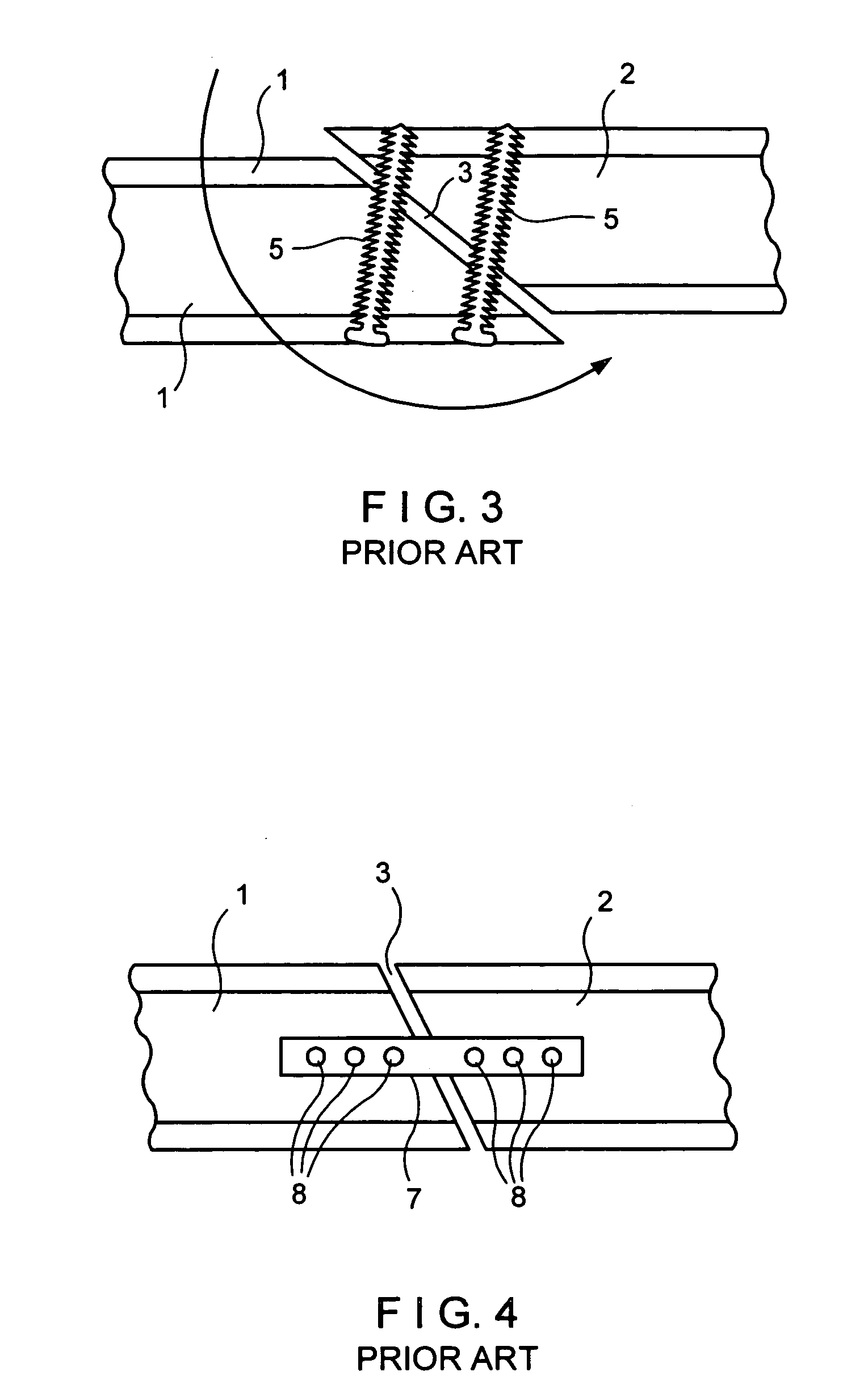
Furthermore, since interfragmentary fixation relies on a single point of contact of the screw within each bone fragment 1,2, there is poor resistance to angular displacements and loss of reduction with axial loading of the bone as shown in FIG. 3.
Even if the screws 5 can be placed perpendicular to the fracture, this manner of fixation is not optimal since the bone is often osteoporotic with the result that the threads of the screws strip and lose purchase as compression is applied.
In addition, placing relatively large diameter holes in a small bone fragment can result in further fracture propagation through the screw hole.
These factors limit the amount of compression that can be achieved by simple interfragmentary bone screw 5.
In addition, this type of fixation is extremely weak in resisting external rotational torque T on the ankle, which can also lead to failure of fixation and a poor clinical result.
Fixation is along a single axis and in one plane and is relatively weak in resisting torsional loads.
In addition, this type of fixation requires bulky plates and a multitude of screws with larger surgical incisions.
Neutralization plates do not provide any load across the fracture site, and may result in longer healing times as well.
However, using a compression plate in the context of a long oblique fracture produces shear forces at the fracture site as previously described, resulting in sliding of the bone fragments with shortening and loss of reduction.
In addition, since the plate is situated predominantly within a single plane, like neutralization plates, they provide only a single plane of fixation with limited ability to control rotational forces.
In addition, the extreme distal nature of the position of this tab would cause the distal fragment to rotate off the corner of the plate.
Intramedullary fixation is not effective for short oblique fractures as it provides no rotational control and allows shortening of the bone.

Method used


Image

  • Bone fixation device and method
  • Bone fixation device and method
  • Bone fixation device and method

Examples


Embodiment Construction

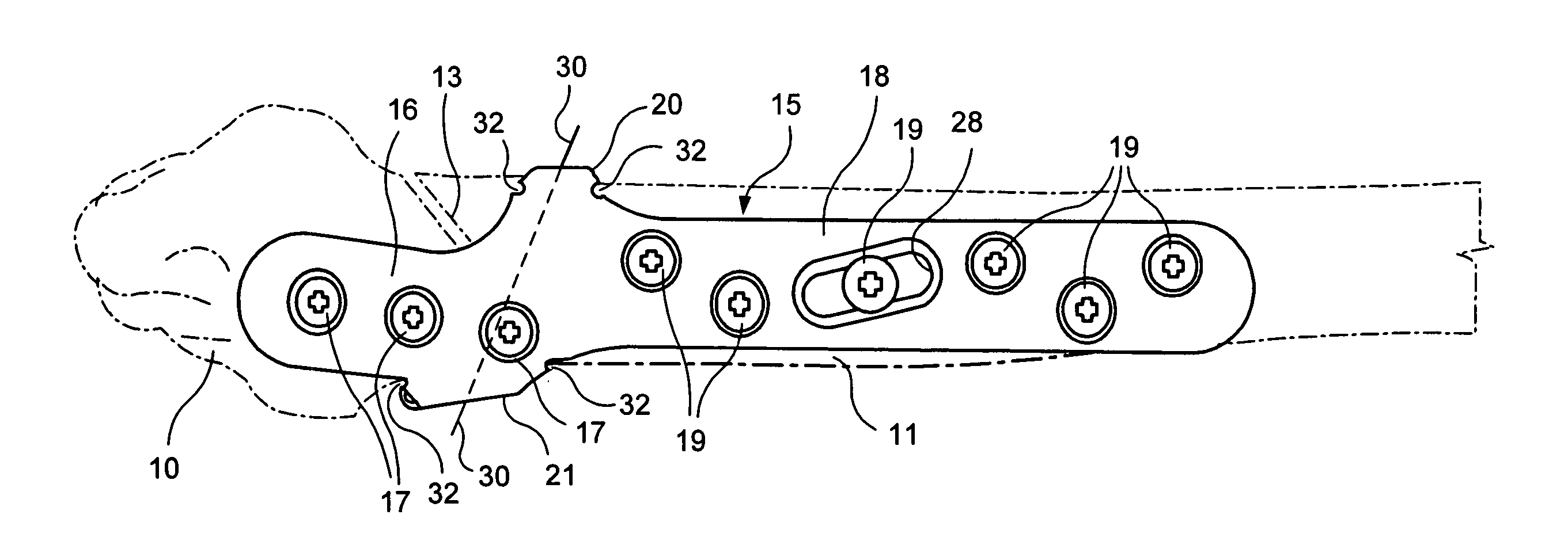
[0047] Referring to FIGS. 5 and 6, therein is shown distal and proximal bone segments or fragments 10, 11 on opposite sides of an oblique fracture 13 of the lateral malleolus bone 14 of the ankle. Although the invention will be described with reference to the lateral malleolus, it is applicable to oblique fractures of other long bones such as the ulna, humerus, tibia, femur etc.

[0048] Attached to the side of the bone 14 is a fixation plate 15 of a fixation implant for fixation of the fracture 13. The fixation plate 15 has a distal portion 16 adapted for being secured by bone screws 17 to the distal fragment 10 and a proximal portion 18 adapted to be secured to the proximal fragment 11 by bone screws 19.

[0049] The fixation plate 15 is made of surgical material such as titanium or stainless steel. Its length and thickness is a function of the bone which is fractured. In a typical case of the lateral malleolus, the thickness of plate 15 will be between 0.025″ and 0.375″ and its lengt...


PUM


Abstract

For fixation of an oblique fracture in a long bone, a fixation plate is placed along the bone across the fracture and tabs extending outwardly from the plate engage the bone at upper and lower surfaces respectively of the proximal and distal fragments of the bone. By applying compressive force to the bone by the tabs, the fragments are subjected to compression force across the fracture and to a torque which opposes bone shortening.

Description

FIELD OF THE INVENTION [0001] The invention relates to a bone fixation device used for fixation of two bone fragments or segments that have an oblique surface of contact, such as the case with an oblique fracture of the lateral malleolus of the ankle. [0002] The invention further relates to a method of bone fixation of such oblique fractures. BACKGROUND AND PRIOR ART [0003] Achieving stable fixation of two bone segments having an oblique contact surface can be difficult. For example, external rotation injuries of the ankle may often result in a short oblique fracture of the lateral malleolus. Because of the oblique orientation of the fracture line, simple apposition of the bone surfaces is nearly always unstable, since axial loading forces on the bone cause sliding of the two bone surfaces along the oblique fracture line and contribute to potential problems of shortening, non-union, and loss of reduction. For fractures involving the lateral malleolus of the ankle, even as little as ...

Claims


Application Information

Patent Timeline
Patent Type & Authority Applications(United States)
IPC IPC(8): A61F2/30
CPCA61B17/8004A61B17/809A61B17/8085A61B17/8061
Inventor MEDOFF, ROBERT J.
Owner MEDOFF ROBERT J
Learn More