Non-destructive evaluation via measurement of magnetic drag force

a technology of non-destructive evaluation and measurement of magnetic drag force, which is applied in the direction of magnetic field measurement using permanent magnets, electric/magnetic measuring arrangements, instruments, etc., can solve the problems of destroying, marring, or otherwise making samples unusable, or less usable, for their original purpose, and wasting a lot of effort in the development of non-destructive evaluation techniques. , to achieve the effect of less time, smaller and more economical apparatus

Inactive Publication Date: 2007-06-07
MAGCANICA
View PDF6 Cites 12 Cited by
  • Summary
  • Abstract
  • Description
  • Claims
  • Application Information

AI Technical Summary

Benefits of technology

[0027] Each of these general applications (e.g., determining magnetic hysteresis loss, detection of local inhomogeneities, detection of purposefully instilled patterns of such inhomogeneities as markers or signatures, detection of the location of an inhomogeneity within a sample, determining which portion of a sample is being analyzed, etc.) has a variety of specific applications. In many of these, drag force measurement often offers benefits over other approaches intended to accomplish the same end. For example, measurement of hysteresis loss in strip samples of electrical steels (standard size strips, commonly called “Epstein strips” after the name of the apparatus in which the hystersis losses of such strips are commonly measured) by drag force measurement requires less time, utilizes smaller and more economical apparatus, and can be used to simultaneously detect local inhomogeneites. It also allows real time measurement of hysteresis losses during the manufacture of such materials. In actuality, there are at least two sources of drag force. One of these is based on the asymmetrical magnetization that arises within a (homogeneous) sample that is moving, or has been moved, through the intense field close to a properly oriented permanent magnet. This asymmetry arises because of magnetic hysteresis in the sample material. Another source of drag force is the appearance of local magnetic “poles” within the sample at the extrema of local inhomogeneities. The presence of these poles (resulting from local inhomogeneity) can be sensed by the forces they exert on the “poles” of the measurement magnet. In most cases, a ferromagnetic material will have both hysteresis and be imperfectly homogenous and therefore show both a finite steady state drag force and a superimposed drag force that varies with position of the material relative to the measurement magnet.
[0028] Yet another aspect of the invention relates to magnetic drag force measurement devices for measuring magnetic drag force not using a sensor having sensing element operably associated with a measurement magnet, but with a sample stage. In this way, drag force on the sample is measured. Here, the sensing element outputs signals indicative of a magnetic drag force experienced by the ferromagnetic sample upon exposure to a pre-determined magnetic field generated by a reference magnet (or reference magnet array) spaced from and in motion relative to the ferromagnetic sample. In preferred embodiments, additional electronics are associated with the sensor so that the signals may be processed, analyzed, and used to generate a meaningful output. In such devices, a drive may be used to move the proximately spaced reference magnet across some or all of one or more surfaces of the sample. In operation, a magnetic drag force is typically measured by moving a proximately spaced reference magnet (or reference magnet array) that provides a magnetic field of pre-determined strength in relation to a magnetic drag force measurement device having a ferromagnetic sample positioned on the sample stage, wherein the sample stage is operably associated with one or more force sensing elements.

Problems solved by technology

By far, most of the tonnage of the steels and other iron alloys used in these applications is ferromagnetic.
The practice of many simple testing techniques results in the sample being destroyed, marred, or otherwise made unusable, or less usable, for its original purpose.
Thus, much effort has been expended in the development of non-destructive evaluation (NDE) techniques, wherein the actual properties of interest, or other properties that unwaveringly correlate with the properties of interest, can be measured on the actual product.
Alternatively, large regions must be inspected by repeated scanning in raster like fashion, a process adding significantly to inspection time and cost.
Electrical steels are often characterized by their magnetic hysteresis loss, since this property is a major determinant of the energy and size efficiency of the transformer, motor, or other device in which the steel is used.
The process is both time consuming and requires relatively sophisticated apparatus.

Method used


Image

  • Non-destructive evaluation via measurement of magnetic drag force
  • Non-destructive evaluation via measurement of magnetic drag force
  • Non-destructive evaluation via measurement of magnetic drag force

Examples


example 1

Detecting Magnetic Drag Force Using a Single Measurement Magnet

[0106] This example describes one preferred embodiment of the invention. In this embodiment the force resisting the motion of a ferromagnetic member through the intense field close to a permanent magnet is measured by the equal and opposite reaction force on the permanent magnet. This force tends to “drag” the magnet in the direction of motion of the ferromagnetic member.

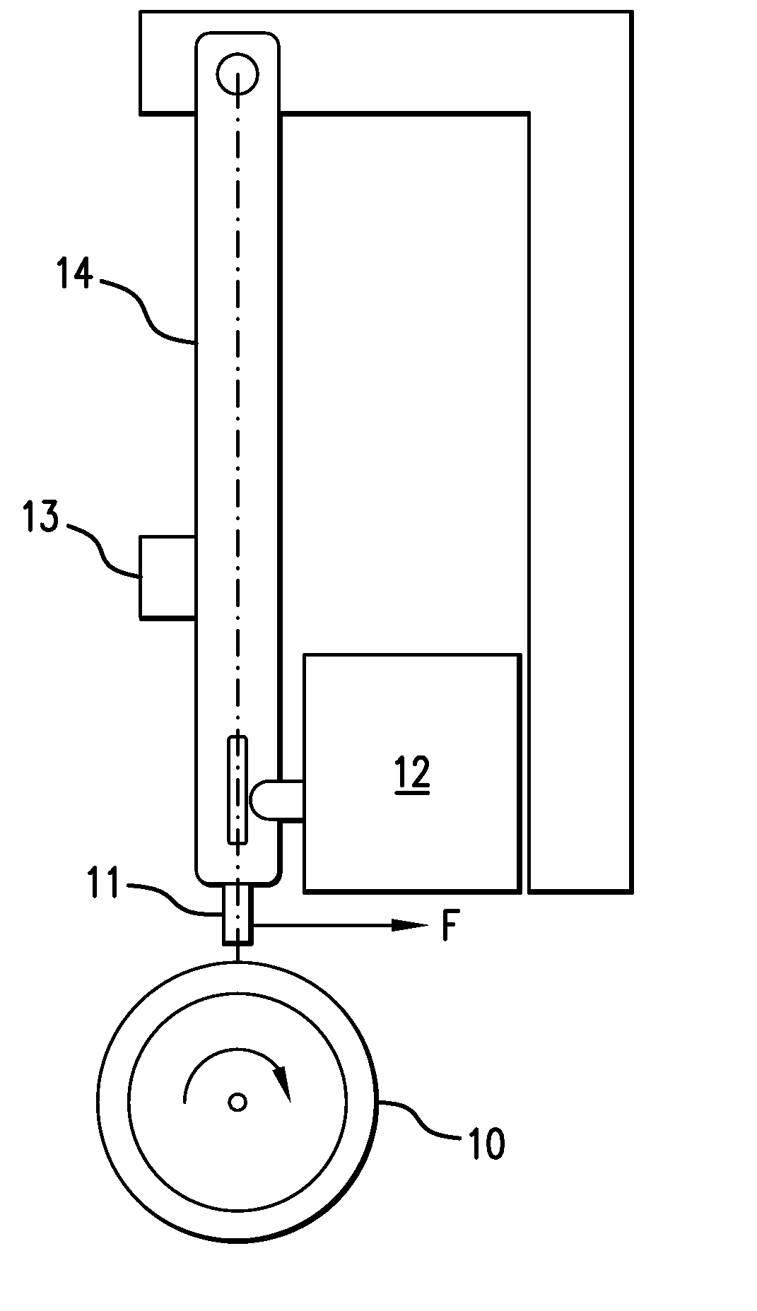
[0107] Photographs of apparatus incorporating this embodiment is shown in FIGS. 12(a) and (b). The essential features are depicted in the schematic diagram of FIGS. 13 (a) and (b). As illustrated in FIG. 13(b), the drag force measuring device (90) employs a single permanent magnet (PM; 100) suspended at the distal end (102) of a pendulum (104) which can rotate freely about shaft (108). The pendulum is biased to bear slightly against the load cell (110) in the absence of any drag (tangential) force on the magnet. This bias prevents the pendulum from los...

example 2

Apparatus for Measuring Magnetic Drag Force on Rotating Ferromagnetic Shafts

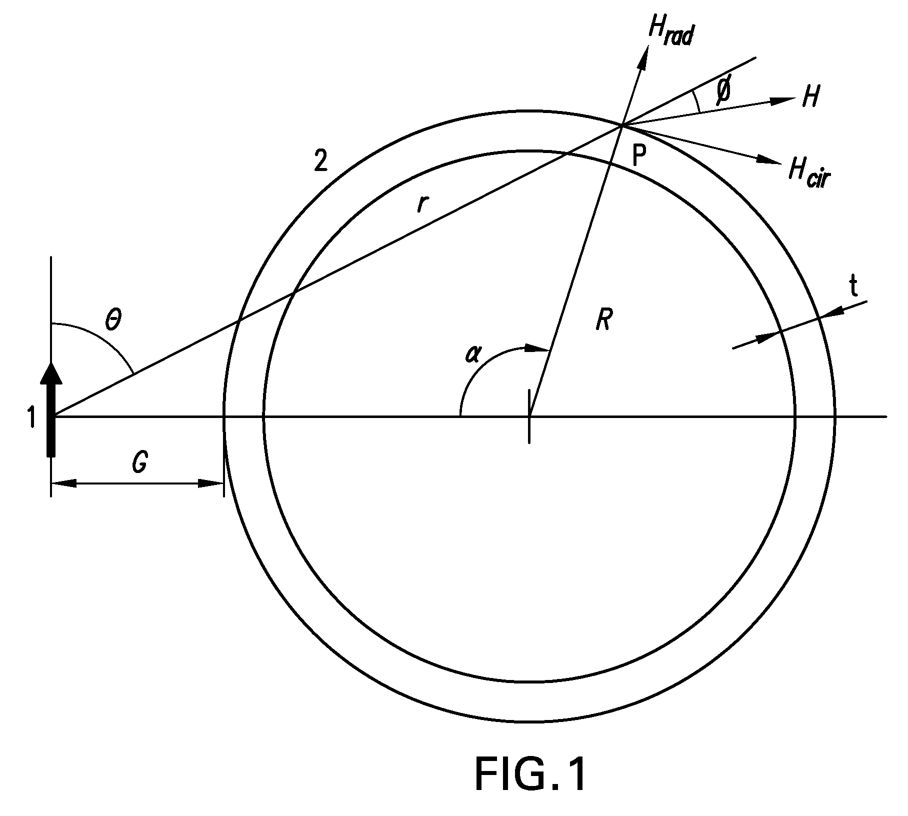
[0111] This example describes a preferred embodiment of the invention that relates a rotating ferromagnetic shaft. A schematic diagram of the apparatus is illustrated in FIG. 5. The shaft was made out of 300M steel (0.43% C, 1.8% Ni, 1.6% Si, 0.8% Cr, 0.4% Mo, 0.07% V, Bal Fe) with an outside radius, R, of 17.5 mm and a wall thickness, t, of 2.5 mm. The coercive force of the material is ±39 Oe. The measurement magnet was of NdFeB type with an energy product of 38MGO, and had dimensions of 2 in. by 0.5 in. by 0.125 in. The load cell was manufactured by Futek (model L2338). The shaft was rotated at slow speed (16.6 rpm) by coupling to a synchronous gear head motor and at high speed (2000 rpm) with a variable speed motor using an O-ring belt.

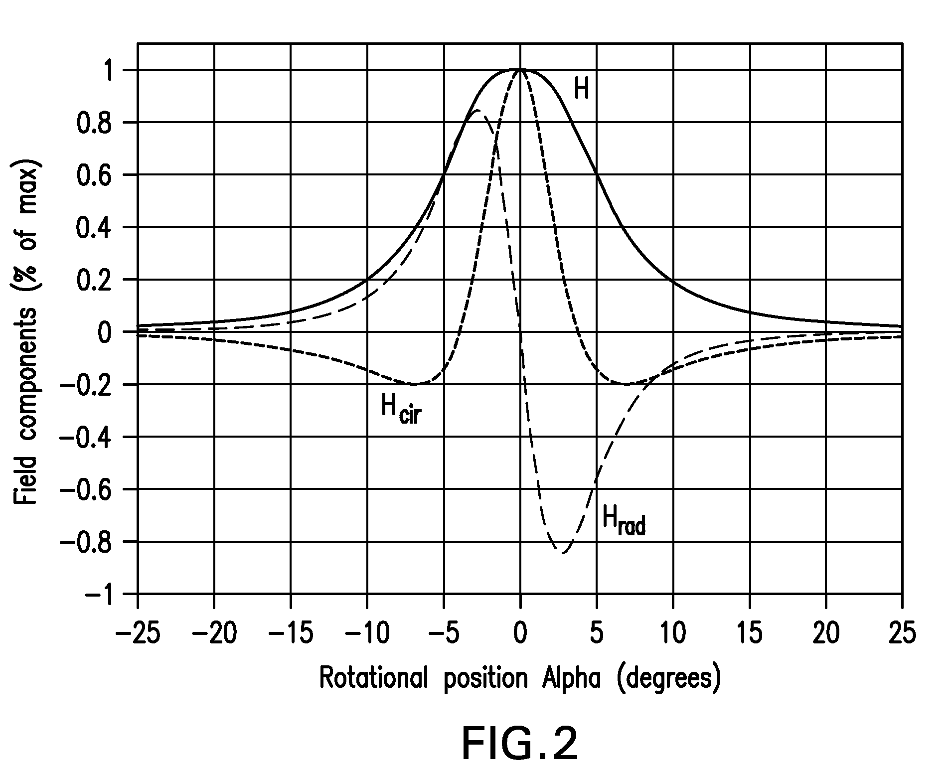
[0112] Measured values of the drag force for the first 22 revolutions of the shaft (characterized in FIG. 5) are shown in FIG. 6 for a variety of gaps between the magnet ...

example 3

Determining Hysteresis Loss by Measuring Drag Force Using a Single Measurement Magnet

1. Abstract.

[0115] This example describes another preferred embodiment, wherein a magnetic drag force measurement device according to the invention (as schematically illustrated in FIG. 15) is used to measure hysteresis loss in a ferromagnetic strip. Thus, this example also describes novel methods for determining hysteresis losses, particularly in thin strips of soft magnetic materials. These methods are based on the measurement of a drag force that arises with movement of a thin sample strip through the strong field existing in the space near a measurement magnet (here, a permanent magnet). Not associated with macro eddy currents, the drag force is shown to originate from the magnetic hysteresis of the material, having in fact an amplitude equal to the product of hysteresis loss and the area of the sample cross section. Correlation within 18% with measurements made by conventional methods is sho...


PUM


Abstract

Sensors for outputting signals indicative of a magnetic drag force between a ferromagnetic sample that is or has been in motion relative to one or more measurement magnets are described. Such sensors include at least one measurement magnet and a sensing element operably associated therewith, such that upon or after exposure of the measurement magnet(s) to a ferromagnetic sample in motion relative thereto, the sensor can sense the drag force, if any, or changes therein, experienced by the measurement magnet. Devices for detecting and/or measuring magnetic drag force that employ one or more of these sensors are also described, as are various applications for such devices.

Description

RELATED APPLICATION [0001] This patent application claims priority to the benefit of U.S. provisional patent application Ser. No. 60 / 731,882, filed 31 Oct. 2005, which application is hereby incorporated by reference for all purposes.TECHNICAL FIELD [0002] This invention concerns sensors and devices suited to non-destructively evaluate ferromagnetic samples. The sensors used in these devices sense the magnetic drag force between a sample and one or more measurement or reference magnets. BACKGROUND OF THE INVENTION [0003] 1. Introduction [0004] The following description includes information that may be useful in understanding the present invention. It is not an admission that any such information is prior art, or relevant, to the presently claimed inventions, or that any publication specifically or implicitly referenced is prior art. [0005] 2. Background [0006] Ferromagnetic materials are a predominant or essential constituent of most of the structures and machines built and utilized ...

Claims


Application Information

Patent Timeline
Patent Type & Authority Applications(United States)
IPC IPC(8): G01B7/16
CPCG01R33/038
Inventor GARSHELIS, IVAN J.TOLLENS, STIJN P.L.
Owner MAGCANICA
Why Eureka
Try Eureka