
Refining member clash control method

a technology of clash control and refiner, which is applied in the field of refiners, can solve the problems of difficult detection of changes in refiner performance, failure to produce a detectable change in sensor output usable, and insufficient prior art approaches referred to above, so as to reduce the chance of plate clashing, reduce the risk and reduce the effect of affecting the quality of the produ

Active Publication Date: 2007-06-07
OVIVO LUXEMBOURG R L
View PDF4 Cites 16 Cited by
  • Summary
  • Abstract
  • Description
  • Claims
  • Application Information

AI Technical Summary

Benefits of technology

[0010] Another of the principal objects of the invention is to create a system that doesn't need to be tuned to a specific frequency. A further object is to create a system that can be used with different refining member patterns or refiner rotational speeds. And a further object of this invention is to create a system of relative simple design.
[0011] The invention comprises a method of responding to the beginning of plate clashing in a pulp refiner with a vibration sensor mounted in direct mechanical connection to the support of a non-rotating refiner member so that the sensor is responsive to axial vibration movement of the support. The method comprises comparing the amplitude of the output signal from the sensor to a baseline value based on the level of vibration associated with the pulp refiner when it is operating without plate clashing, and when the signal exceeds the baseline value, then taking an action intended to help alleviate the plate clashing. Such action can be sounding an alarm, changing the refining process, or both.
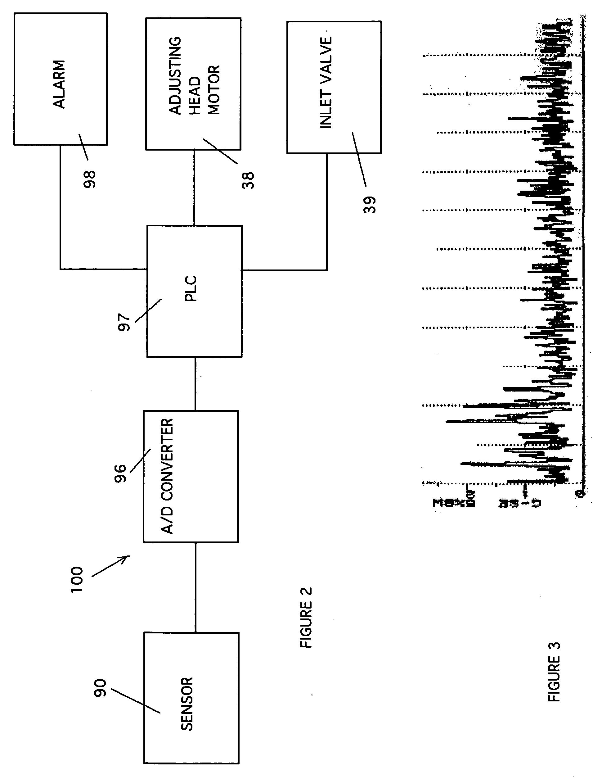
[0012] The invention also comprises a method and a control system for a refiner for pulp or like materials, the control system comprising a sensor mounted in direct mechanical connection to a non-rotating refining member so that the sensor is responsive to axial vibration movement of the support, and an analog to digital converter connected to the output of the sensor. The method and controller also include a controller connected to the analog to digital converter and responsive to the output from the analog to digital converter to compare the amplitude of the output signal from the sensor to a baseline value based on the level of vibration associated with the pulp refiner when it is operating without plate clashing. When the signal exceeds the baseline value, an action is taken to help alleviate the plate clashing.
[0013] This invention is thus relative simple in construction for it can be easily connected to the refiner stationary supports and connected to a conventional refiner Programmable Logic Controller (PLC).

Problems solved by technology

The prior art approaches referred to above are not believed to be adequate for preventing all plate clashing, especially as can be experienced with low pulp consistency refiners.
In low pulp consistency refiners, less pulp material flows through the refiner, which makes changes in refiner performance harder to detect.
Experimentation has determined that a sensor that only looks at radial vibration or a sensor location that is not directly mechanically connected to a stationary head fails to produce a detectable change in sensor output usable for indicating plate clashing is occurring.

Method used


Image

  • Refining member clash control method
  • Refining member clash control method
  • Refining member clash control method

Examples


Embodiment Construction

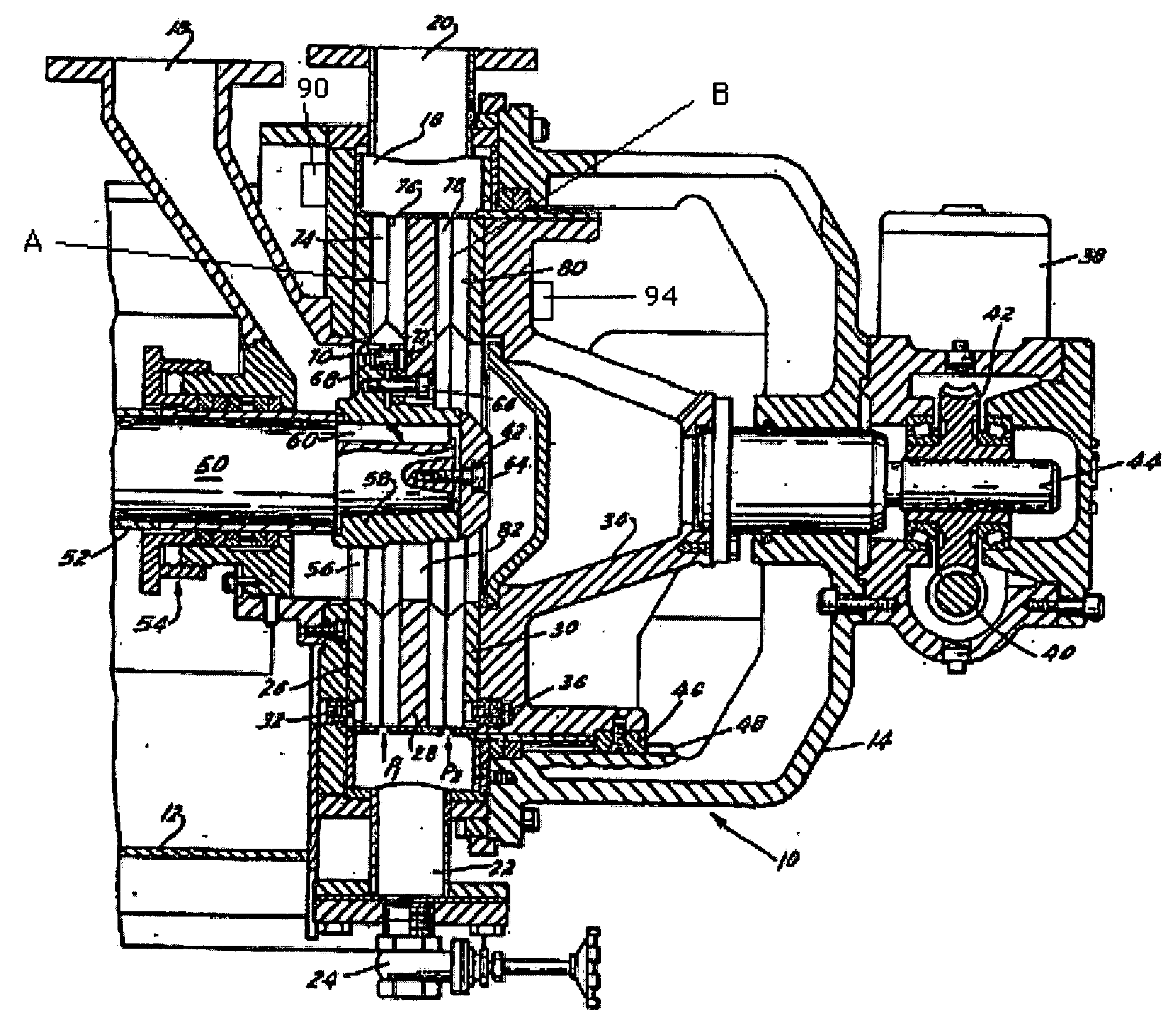
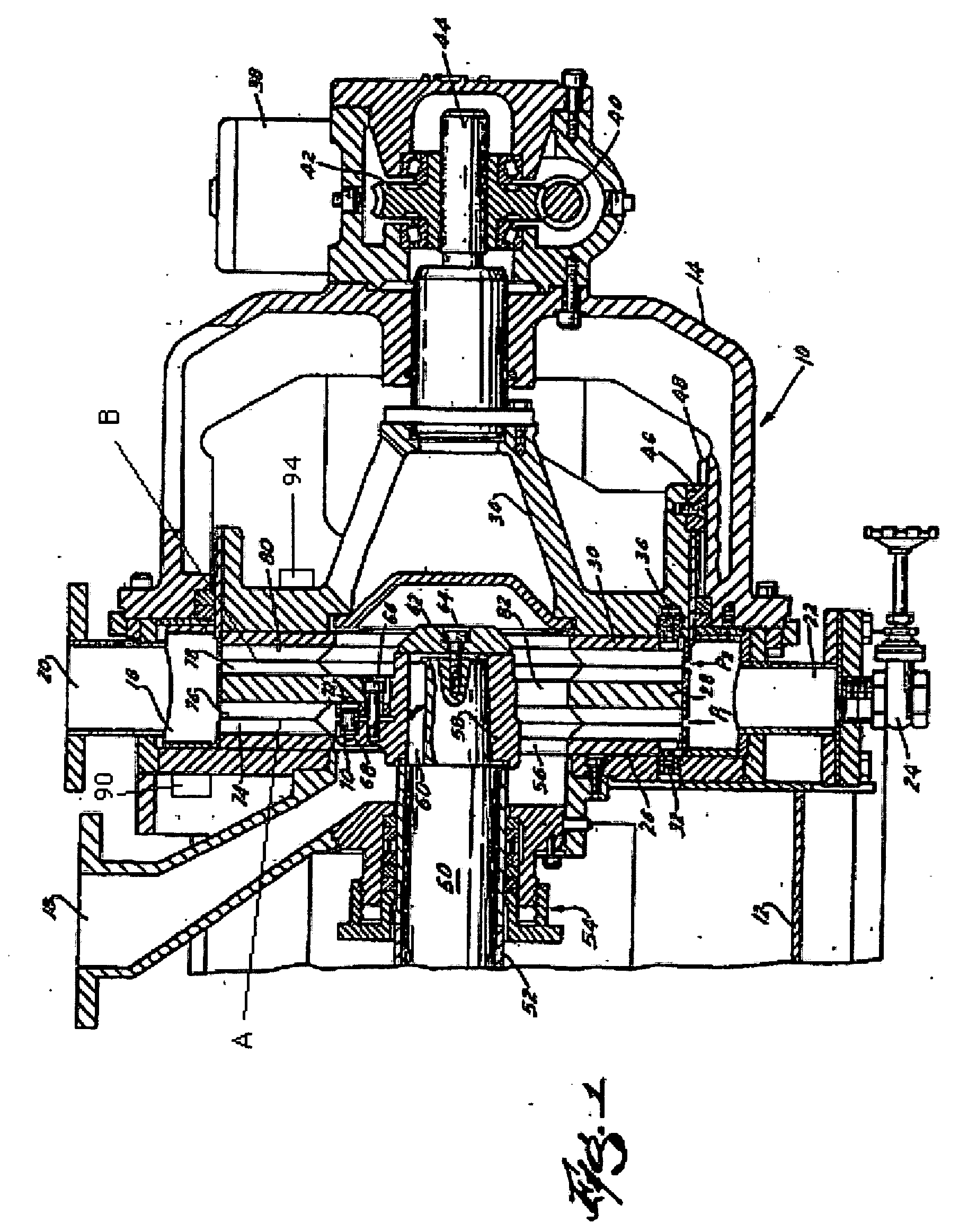
[0018] Referring first to FIG. 1, there is shown a refiner having a housing 10 including several bolted-together sections, two of which are shown at 12 and 14. The housing defines a stock chamber 16 and has an inlet 18 for admission of pulp, e.g., from the outlet of a pump (not shown) or an inlet valve 39 (shown schematically in FIG. 2), a first outlet 20 for evacuation of refined pulp, at least in part under the action of centrifugal force, and a second outlet 22 that is normally closed by a suitable valve 24. The outlet 20 extends upwardly and the outlet 22 extends downwardly. The valve 24 is opened when the attendants wish to drain the liquid carrier for large pulp pieces or the like from the chamber 16.

[0019] The chamber 16 accommodates three refining members 26, 28, 30, here shown as coaxial discs having identical outer diameters. In other embodiments (not shown), only two discs can be used, or two back-to-back discs can be used instead of the single disc 28. In still other em...


PUM

PropertyMeasurementUnit
strength potentialaaaaaaaaaa
paper strength propertiesaaaaaaaaaa
distanceaaaaaaaaaa

Abstract

A method and a control system for a refiner for pulp or like materials, the control system comprising a sensor mounted in direct mechanical connection to a non-rotating refining member so that the sensor is responsive to axial vibration movement of the support, and an analog to digital converter connected to the output of the sensor. The method and control system also include a controller connected to the analog to digital converter and responsive to the analog to digital converter to compare the amplitude of the output signal from the sensor to a baseline value based on the level of vibration associated with the pulp refiner when it is operating without plate clashing. When the signal exceeds the baseline value, an action is taken to help alleviate the plate clashing.

Description

BACKGROUND OF THE INVENTION [0001] The present invention relates to refiners for papermaking pulp or the like, and more particularly to improvements in refiners whose inlet admits stock for treatment by comminuting projections (e.g., ribs) on the neighboring surfaces of non-rotating refining members and rotary refining members. [0002] The Pulp and Paper Industry uses pulp refiners to prepare papermaking fiber for production of paper products. The purpose of this refining process is to increase the strength potential of the pulp slurry before the pulp is formed into a sheet of paper. This is accomplished by passing the paper pulp between sets of refining members (also referred to as plates or discs) consisting of alternating bars and grooves that are in close proximity to each other. The gap between these plates is adjustable and can be as little as 2 thousandths of an inch. One of the plates rotates while the other plate in the set is stationary or non-rotating. The papermaking fibe...

Claims


Application Information

Patent Timeline
Patent Type & Authority Applications(United States)
IPC IPC(8): B02C25/00
CPCD21D1/002D21D1/30
Inventor CROSSLEY, BRUCE R.SHELOMIS, DWIGHT
Owner OVIVO LUXEMBOURG R L
Learn More