

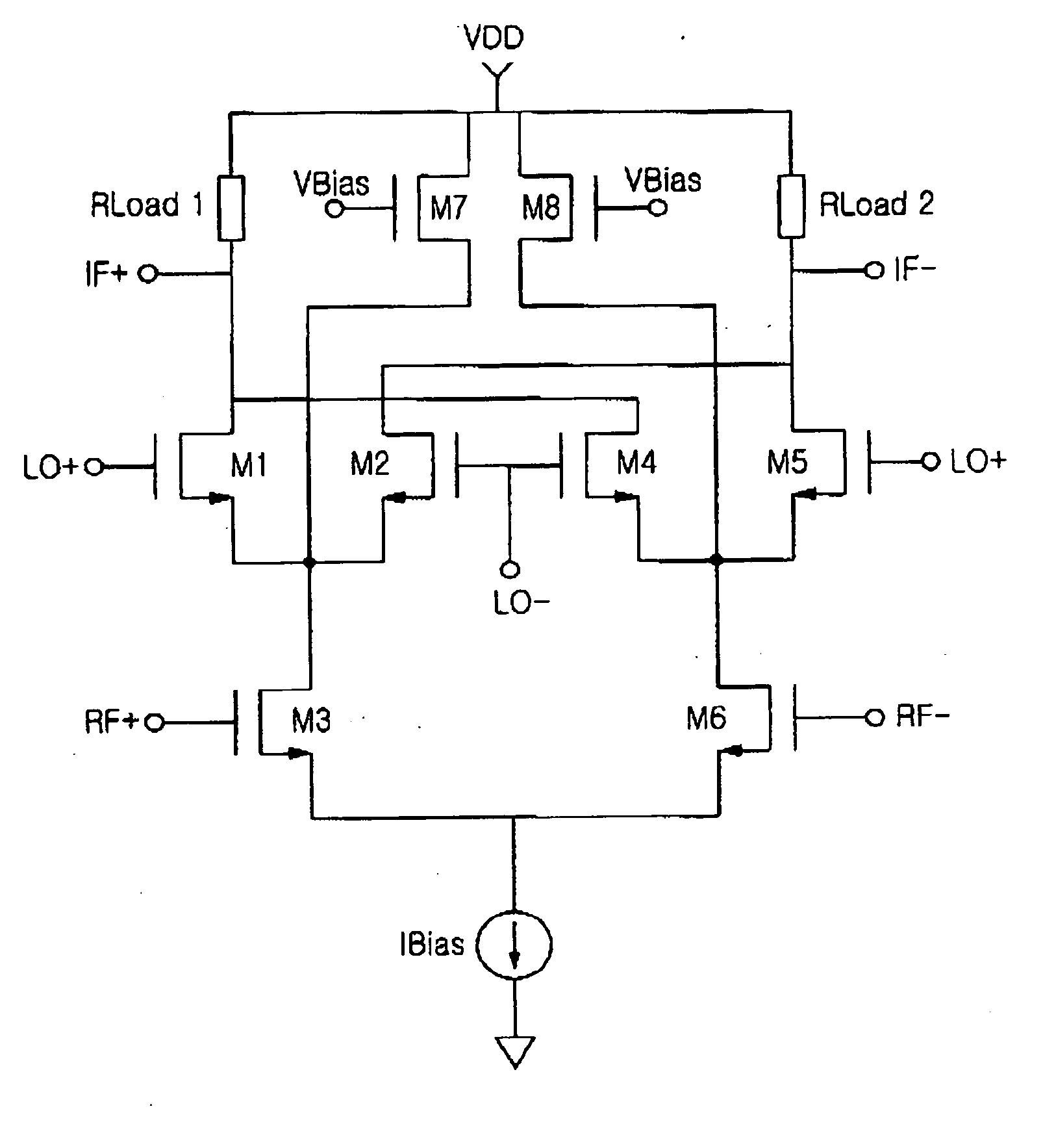
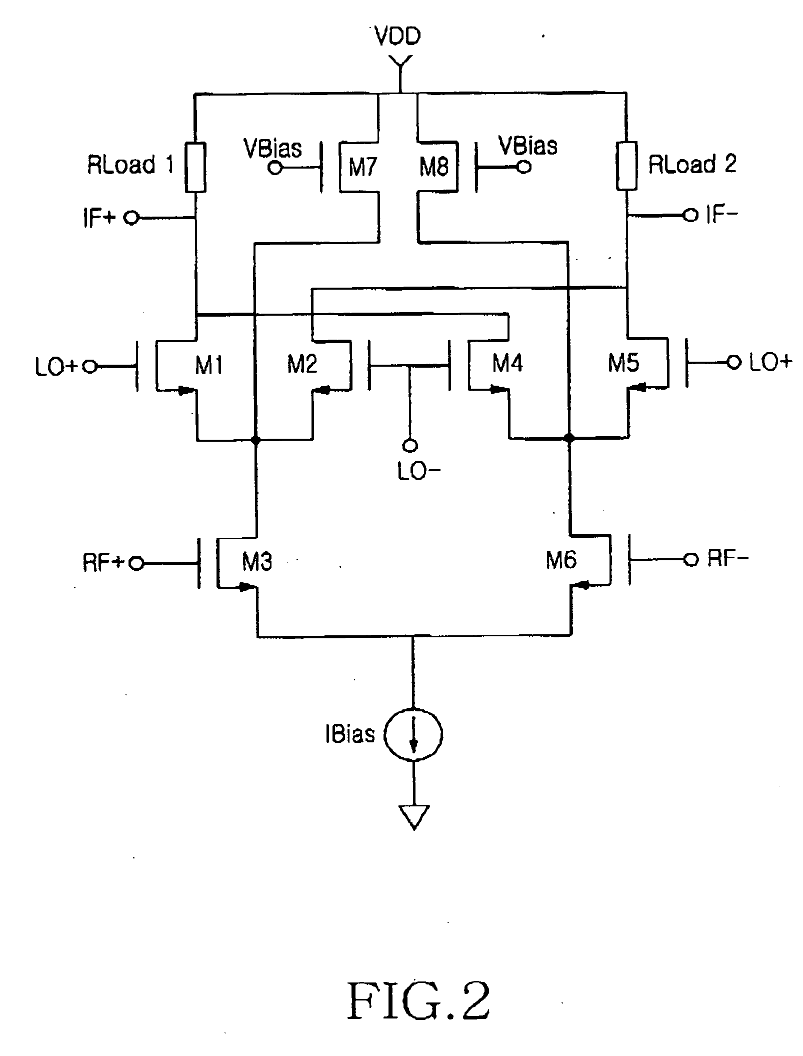
CMOS mixer for use in direct conversion receiver
a technology of a communication system and a mixer, applied in the field of mixers for use in direct conversion receivers, can solve the problems of increasing parasitic capacitance, increasing impedance (rds) viewed from the switch side, and additional flicker noise from current bleeding circuitry
- Summary
- Abstract
- Description
- Claims
- Application Information
AI Technical Summary
Benefits of technology
Problems solved by technology
Method used
Image

Examples
Embodiment Construction
[0044] Preferred embodiments of the present invention will now be described in detail with reference to the annexed drawings. In the following description, a detailed description of known functions and configurations incorporated herein has been omitted for conciseness.
[0045] In designing the present invention the following facts to solve the problems of the mixers according to prior art have been taken into consideration:
[0046] (1) the current of an RF input terminal should be large for a good conversion gain;
[0047] (2) the current of an LO switching terminal should be low to lower the height of a pulse of flicker noise;
[0048] (3) the size of an LO switch should be large enough to reduce MOS-inherent flicker noise;
[0049] (4) if the size of an LO increases, parasitic capacitance Cp will also increase;
[0050] (5) if parasitic capacitance increases, flicker noise will also increase by an indirect mechanism; and
[0051] (6) a small inductor size, a high inductor Q value, and a high...
PUM
 Abstract
Description
Claims
Application Information