Method for producing alignment layer for liquid crystal panel

a liquid crystal panel and alignment layer technology, applied in the direction of thin material processing, instruments, chemistry apparatus and processes, etc., can solve the problems of poor reliability, reduced process yield, difficult to solve the rubbing alignment technique, etc., and achieve high anchoring energy, good uniformity, and simplify the alignment process

Active Publication Date: 2007-06-07
IND TECH RES INST
View PDF5 Cites 2 Cited by
  • Summary
  • Abstract
  • Description
  • Claims
  • Application Information

AI Technical Summary

Benefits of technology

[0023] A method for producing an alignment layer for a liquid crystal panel provided by the present invention is mainly to modify an alignment film in a fixed direction and at a fixed angle by using an atmospheric pressure plasma source to form a uniform and isotropic alignment layer on the surface of the substrate. Therefore, the resultant alignment layer has good uniformity and high anchoring energy, and the pre-tilt angle can be selected as desired. In addition, because the modification of the alignment film on the surface of the substrate is performed by an atmospheric pressure plasma source, there are no problems of static charge generation, dust pollution and the like as in the prior arts. The method of the present invention does not require vacuum equipment. Compared with general vacuum plasma alignment techniques, the method of the present invention simplifies the alignment process and not only saves the time and space that would be required for the creation of a vacuum, but also is not restricted by the size of the vacuum equipment. Therefore, the method of the present invention is suitable for treating the surface of an alignment layer of large-sized liquid crystal panels, and can significantly reduce manufacture costs.

Problems solved by technology

However, as progress is made towards the technical aims of high luminosity, large size, wide visual angle, and so on, the rubbing alignment technique has many problems that are difficult to solve.
For example, the problems of dust pollution, residual static charge, rubbing defects and the like that are caused by rubbing a thin film in the rubbing process can easily result in reduced process yield and poor reliability.
However, there are technological bottlenecks such as anchoring energy, image sticking and the like that remain to be solved.
Moreover, the problems of light bulb life and light flicker when using an exposure machine severely impact the stability.
Because there is a need for using high vacuum equipment and static charge elimination equipment in the process of ion beam alignment, the cost is very expensive.
Furthermore, the creation of the vacuum needs a lot of time and is restricted by the size of the equipment.
For larger-sized panels, it needs specially-made equipment that is extremely expensive.
In addition, the problem of the relatively short life of the ion gun used in the process has not been overcome.
However, all of the plasma beam alignment techniques that have been disclosed in publications or patents use vacuum plasma equipment and thus the cost is very expensive.
Furthermore, the creation of vacuum needs a lot of time and is restricted by the size of the equipment.
For larger-sized panels, specially-made equipment is needed that is extremely expensive and occupies space for the equipment and the like.
Thus, the plasma beam alignment technique also remains in the stage of laboratory development and hasn't attained industrial applicability.

Method used


Image

  • Method for producing alignment layer for liquid crystal panel
  • Method for producing alignment layer for liquid crystal panel

Examples


Embodiment Construction

[0026] The modes for carrying out the present invention are illustrated in the following by specific embodiments. A person skilled in the art can readily understand other advantages and effects of the present invention from the contents disclosed in this description. The present invention can also be carried out or applied by other differing embodiments. Details of this specification can be modified and altered based on different viewpoints and applications without departing from the scope of the present invention.

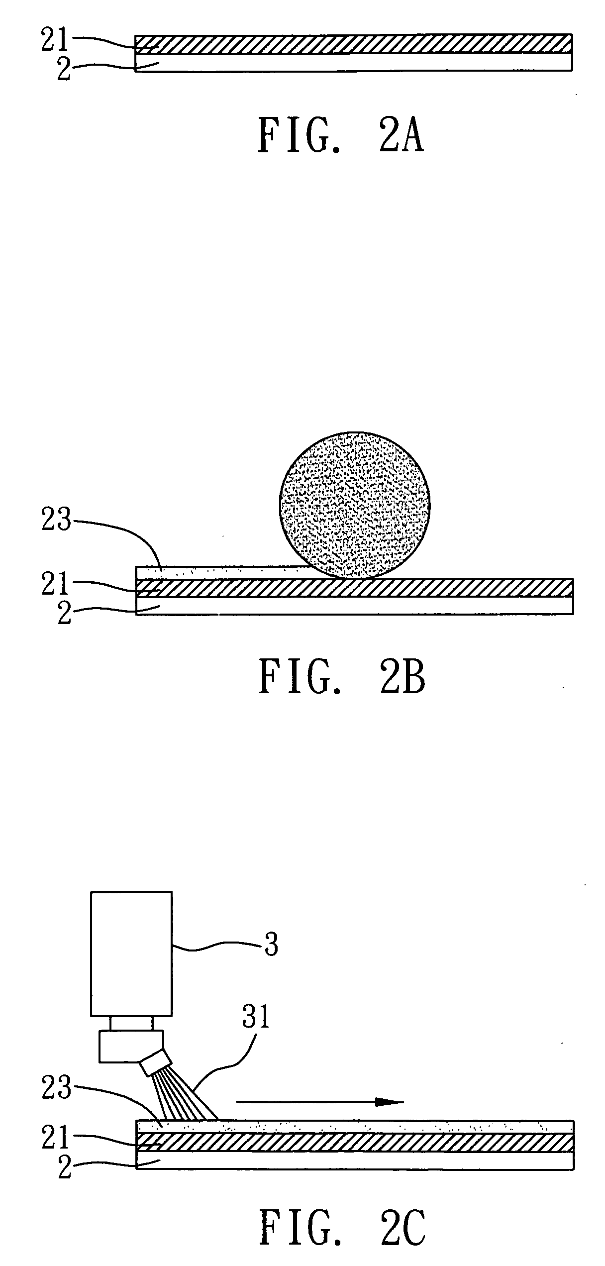
[0027]FIGS. 2A to 2C are views according to a preferred embodiment of the present invention. It should be noted that the appended views are simplified diagrams, and they are intended to explain the basic method of the present invention in a concise manner. Thus, only the steps that are related to the present invention are depicted in these diagrams, and the steps shown in the diagrams are not delineated to the extent needed for practical application. In fact, the process ...


PUM

PropertyMeasurementUnit
pressureaaaaaaaaaa
vacuum pressureaaaaaaaaaa
pressureaaaaaaaaaa

Abstract

A method for producing an alignment layer for a liquid crystal panel, which is produced by modifying an alignment film in a fixed direction and at a fixed angle by using an atmospheric pressure plasma source to form a uniform and isotropic alignment layer on the surface of the substrate. The resultant alignment layer has good uniformity and high anchoring energy, and the pre-tilt angle can be selected as desired. In addition, there are no problems with static charge generation, dust pollution and the like as in the prior arts. The method of the present invention is not restricted by vacuum apparatuses that need ion alignment or vacuum plasma alignment and the like and is not restricted by the size of the equipment. Therefore, the method of the present invention is suitable for treating the surface of an alignment layer of a large size liquid crystal panel.

Description

FIELD OF THE INVENTION [0001] The present invention relates to an alignment technique for a surface of a substrate, and more particularly, to a method for producing an alignment layer for a liquid crystal panel. BACKGROUND OF THE INVENTION [0002] In recent years, flat panel displays have become more and more integrated into daily life. Displays can be distinguished into two main types: cathode-ray tube displays and liquid crystal displays. Among them, the liquid crystal display (LCD) has advantages of light weight, small size, full-color display, less radiation, digitization, high definition, energy-saving and the like compared with the traditional cathode-ray tube displays. As a result, the liquid crystal display has definitely become the main trend in display technology. [0003] The composition and the luminous principle of a liquid crystal display are very different from a cathode-ray tube. Briefly, a liquid crystal display controls the geometry of liquid crystals by using an elec...

Claims


Application Information

Patent Timeline
Patent Type & Authority Applications(United States)
IPC IPC(8): C09K19/00G02F1/1337
CPCY10T428/1005G02F1/13378C09K2323/02
Inventor TANG, HUANG-CHINLIN, CHUN-HUNGCHEN, CHIH-WEIWU, CHIN-JYITSAI, CHEN-DERLEE, CHIN-YANG
Owner IND TECH RES INST
Why Eureka
Try Eureka