Venous valve with sinus

a technology of venous valves and sinuses, applied in the field of venous valves, can solve the problems of reducing the flow of oxygenated blood to the brain, and possibly reducing the volume of blood available to the hear

Inactive Publication Date: 2007-06-07
BOSTON SCI SCIMED INC
View PDF99 Cites 27 Cited by
  • Summary
  • Abstract
  • Description
  • Claims
  • Application Information

AI Technical Summary

Benefits of technology

[0011] Embodiments of the venous valve include a venous valve frame and valve leaflets that can be implanted through minimally-invasive techniques into the body lumen. In one example, embodiments of the apparatus and method for valve replacement or augmentation may help to maintain antegrade blood flow, while decreasing retrograde blood flow in a venous system of individuals having venous insufficiency, such as venous insufficiency in the legs. Use of valve embodiments can also be possible in other portions of the vasculature.

Problems solved by technology

In the legs and arms, the transit time of this increased arterial pressure is delayed, resulting in a temporary drop in venous pressure.
Venous pressure drops as blood flow responds to body position change and gravity, thereby reducing the volume of blood available to the heart and possibly reducing the flow of oxygenated blood to the brain.
In such a case, a person could become light headed, dizzy, or experience syncope.
Compromised valves, however, would allow reverse blood flow and pooling in the lower legs resulting in swelling and ulcers of the leg.
The absence of functioning venous valves can lead to chronic venous insufficiency.
Techniques for both repairing and replacing the valves exist, but are tedious and require invasive surgical procedures.
Prosthetic valves can be transplanted into the venous system, but current devices are not successful enough to see widespread usage.
One reason for this is the very high percentage of prosthetic valves reported with leaflet functional failures due to excessive protein deposit, cell growth and thickening, and thrombosis.
These failures have been blamed primarily on improper sizing and tilted deployment of the prosthetic valve.
Such contact or proximity can cause regions of blood stasis or near stasis, and can result in increased thrombus formation.
In addition, contact can result in disruption of endothelial or other tissue at the contact point, further increasing the likelihood of thrombosis or increased tissue deposits or healing response.
Further, such contact or proximity can result in valve leaflet(s) being stuck to the vessel wall, or otherwise unable to move properly, thereby rendering the valve less functional or completely non-functional.

Method used


Image

  • Venous valve with sinus
  • Venous valve with sinus
  • Venous valve with sinus

Examples


Embodiment Construction

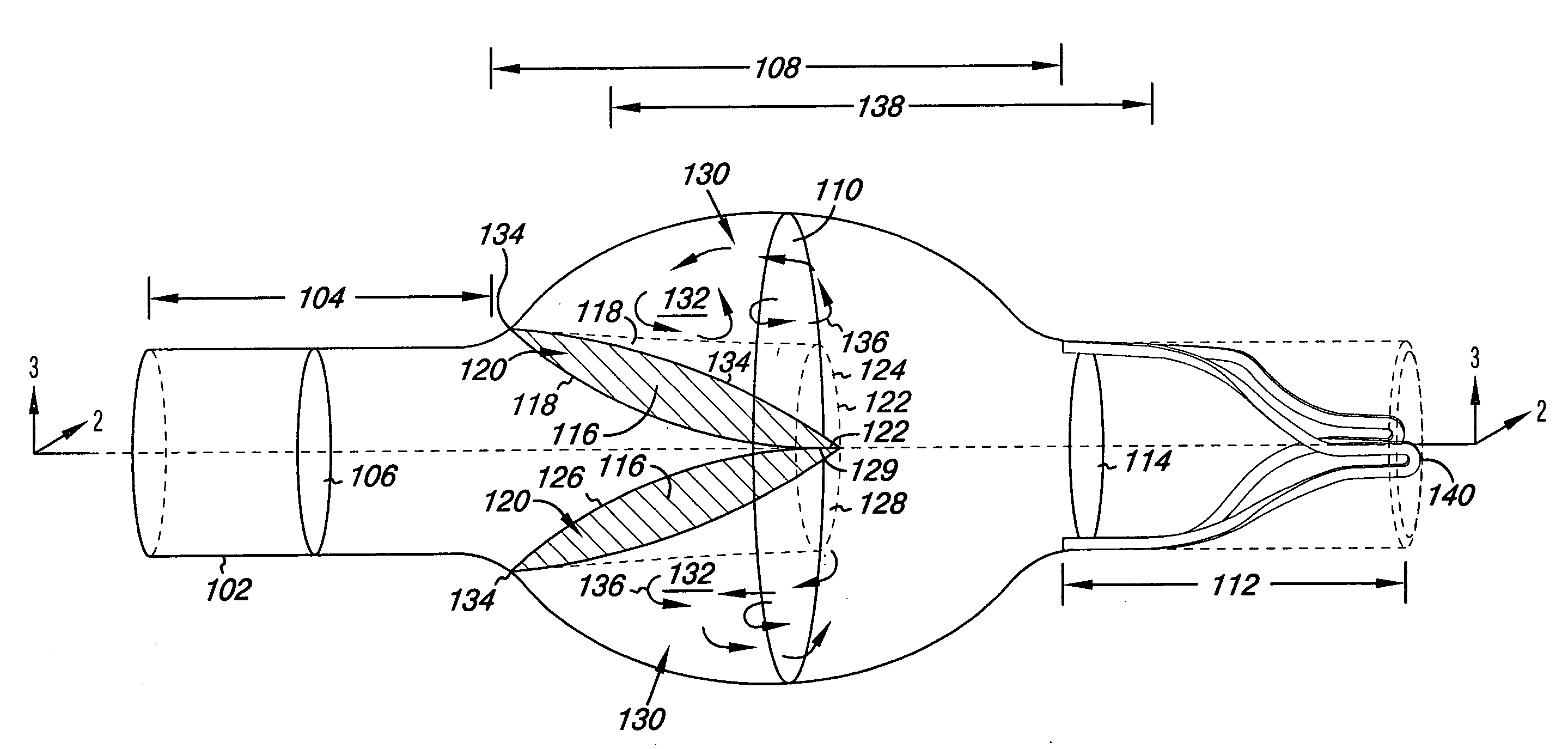
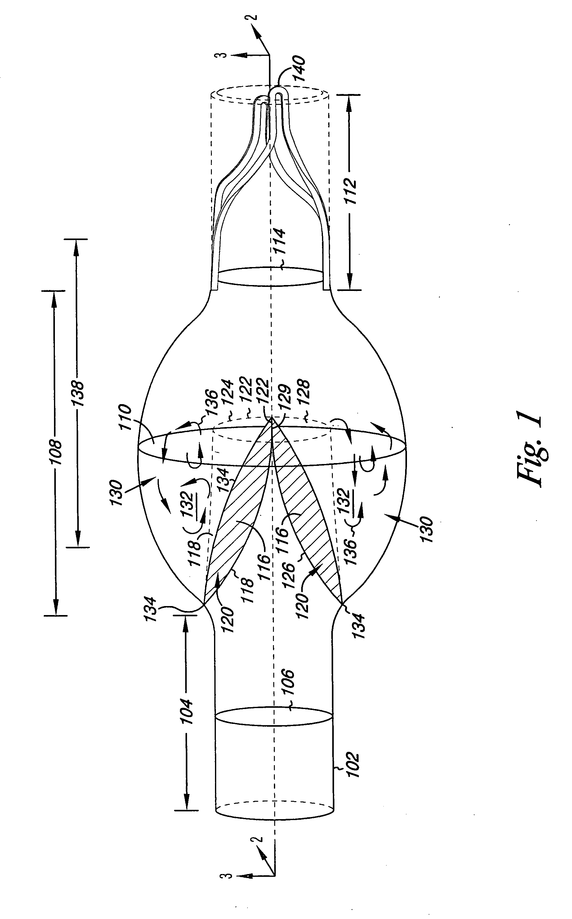
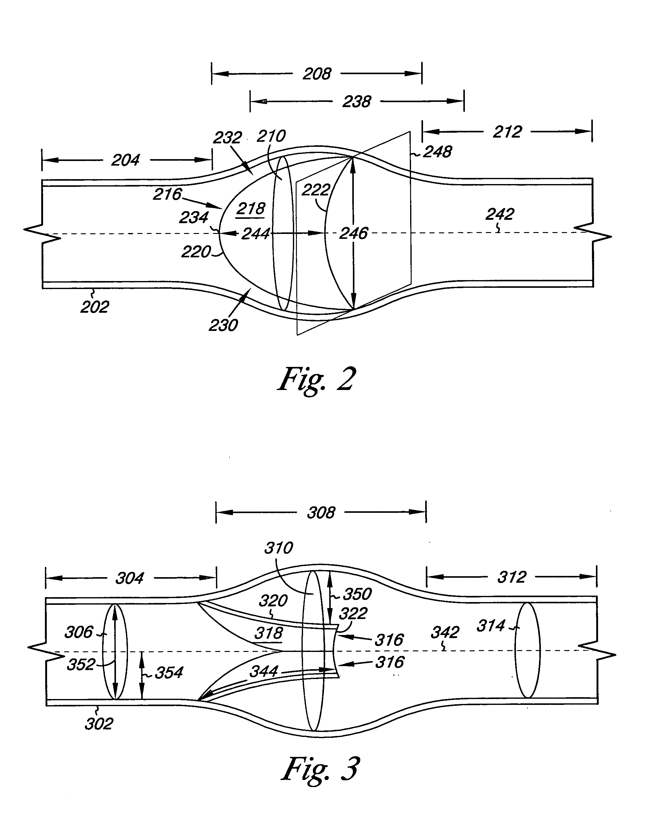
[0010] Embodiments of the present disclosure are directed to vascular medical devices and methods for valve replacement and / or augmentation. Particularly, the present disclosure provides venous valves and methods for forming the venous valve. Various embodiments of the present disclosure can be used to replace and / or augment an incompetent valve in a body lumen. As used herein, “body lumen” can include, but is not limited to, veins, arteries, lymph vessels, ureter, cerebrospinal fluid track, or other body cavity, vessel, or duct.

[0011] Embodiments of the venous valve include a venous valve frame and valve leaflets that can be implanted through minimally-invasive techniques into the body lumen. In one example, embodiments of the apparatus and method for valve replacement or augmentation may help to maintain antegrade blood flow, while decreasing retrograde blood flow in a venous system of individuals having venous insufficiency, such as venous insufficiency in the legs. Use of valve...


PUM

PropertyMeasurementUnit
distanceaaaaaaaaaa
distanceaaaaaaaaaa
distanceaaaaaaaaaa

Abstract

A venous valve-with a structural member and valve leaflets that provide a sinus.

Description

CROSS-REFERENCE TO RELATED APPLICATIONS [0001] This application is a Continuation-in Part of U.S. application Ser. No. 11 / 232,403, filed Sep. 21, 2005, the specification of which is incorporated by reference herein.FIELD OF THE DISCLOSURE [0002] The present disclosure relates to vascular medical devices and methods; and more particularly to venous valves and methods for forming the venous valve frame. BACKGROUND OF THE DISCLOSURE [0003] Venous blood flow returns de-oxygenated blood from the distal extremities to the heart via two mechanisms. The first is the perfusion pressure resulting from the arterial blood flow through tissue to the venous circulation system. Where arterial pressure prior to perfusion may be 60 to 200 mm Hg, the resulting venous pressure is typically 10 to 40 mm Hg. The second mechanism is the calf muscle, which, when contracted, compresses the veins (tibial and peroneal) overlying the bone and, through a system of valves, directs blood flow toward the heart. Th...

Claims


Application Information

Patent Timeline
Patent Type & Authority Applications(United States)
IPC IPC(8): A61F2/06
CPCA61F2/2418A61F2/2436A61F2/2475A61F2/06A61F2250/0098Y10T29/49405A61F2220/005A61F2220/0058A61F2220/0066A61F2230/0013A61F2220/0016A61F2210/0014A61F2/2412
Inventor DRASLER, WILLIAM J.JENSON, MARK L.HILL, JASON P.SOGARD, DAVID J.HAVERKOST, PATRICK A.SHOEMAKER, SUSAN M.
Owner BOSTON SCI SCIMED INC
Why Eureka
Try Eureka