Oscillating water column energy accumulator

a technology of oscillating column and energy accumulator, which is applied in the direction of electric generator control, couplings, fluid couplings, etc., can solve the problems of premature wear of parts, reduced efficiency of non-rectifying turbines, and reduced efficiency of turbines, so as to protect against wear

Active Publication Date: 2007-06-14
AOE ACCUMULATED OCEAN ENERGY
View PDF10 Cites 14 Cited by
  • Summary
  • Abstract
  • Description
  • Claims
  • Application Information

AI Technical Summary

Benefits of technology

[0012] A machine powered by the accumulated fluid may be located remotely from the transducers and in particular the corrosive environment of a body of saltwater. With the transducers and the machine connected together as a closed system and the accumulated fluid being a fluid other than saltwater or another corrosive, the machine is further protected against wear.

Problems solved by technology

Although ingenious, these generators suffer from a number of disadvantages.
First, the corrosive mixture of salt water and air typically found inside the chamber can cause parts, for example the turbine, to wear prematurely.
Second, a turbine, which is a relatively expensive component, is required to harness the energy of each such water column; in other words, if a series of such chambers were constructed side-by-side, each would require its own turbine because of the difficulty of synchronizing the chambers' air-flows so as not to interfere with each other.
Third, the bi-directional airflow pumped by the oscillating water column conventionally demands a self-rectifying turbine, typically a Wells turbine, which is generally less efficient than a non-rectifying turbine, particularly under large and small wave conditions.

Method used


Image

  • Oscillating water column energy accumulator
  • Oscillating water column energy accumulator
  • Oscillating water column energy accumulator

Examples


Embodiment Construction

[0030] The invention will be more fully illustrated by the following detailed description of non-limiting specific embodiments in conjunction with the accompanying drawing figures. In the figures, similar elements and / or features may have the same reference label. Further, various elements of the same type may be distinguished by following the reference label with a second label that distinguishes among the similar elements. If only the first reference label is identified in a particular passage of the detailed description, then that passage describes any one of the similar elements having the same first reference label irrespective of the second reference label.

BRIEF DESCRIPTION OF THE DRAWINGS

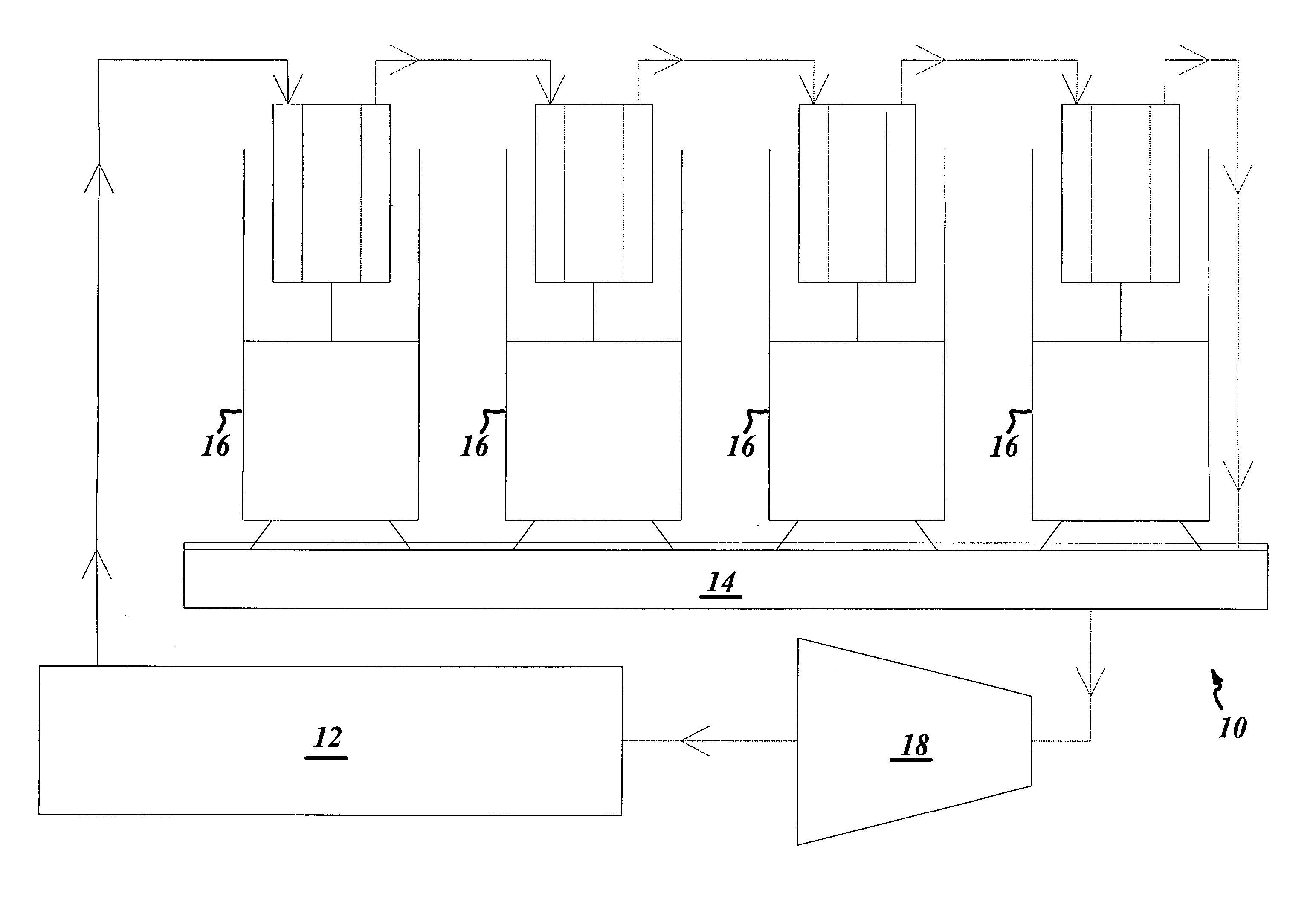
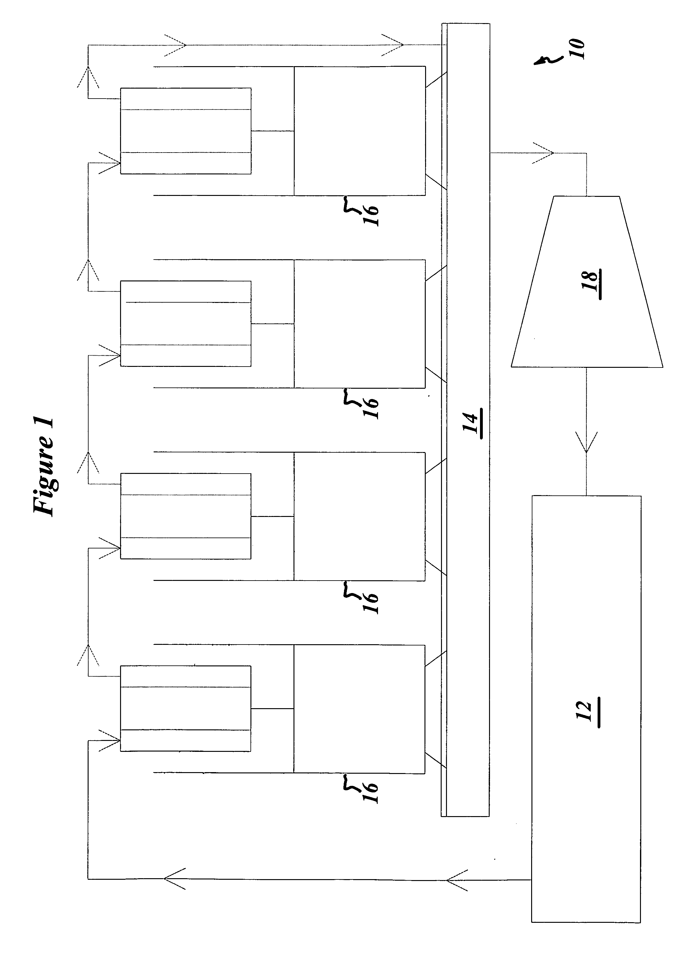
[0031]FIG. 1 is a schematic view of one embodiment of an apparatus for accumulating energy from an oscillating water column according to one aspect of the present invention, the apparatus having a low-pressure-float, a high-pressure-float, a plurality of transducers connected together in ser...


PUM


Abstract

The present invention relates to a method and apparatus for accumulating energy from an oscillating water column by transducing the water column oscillations to compress a fluid and accumulating the compressed fluid.

Description

BACKGROUND OF THE INVENTION [0001] 1. Field of the Invention [0002] The present invention relates to a method and apparatus for accumulating energy from an oscillating column of water. [0003] 2. Description of Related Art [0004] Electrical generators that harness the power of an oscillating water column have been known for at least a number of decades. In general, these generators include a large chamber built at the shoreline of a body of water, the chamber both rising above and submerging below the water level at the shoreline. Such chambers are typically built along steep shorelines, or even into the faces of cliffs, where the difference in height between wave crests and wave troughs is pronounced. [0005] The chamber includes a first opening submerged below water level and a second opening that vents to the atmosphere via a turbine, such that the chamber contains a column of water having a height approximately equal to the water level outside the chamber. As the crests and trough...

Claims


Application Information

Patent Timeline
Patent Type & Authority Applications(United States)
IPC IPC(8): H02K35/00
CPCF03B13/142Y02E10/32Y02E10/38Y02E10/30F03B13/1875F03B13/24
Inventor SIEBER, JOSEPH D.
Owner AOE ACCUMULATED OCEAN ENERGY
Why Eureka
Try Eureka