Patch antenna element and application thereof in a phased array antenna

a phased array and antenna element technology, applied in the direction of antenna earthings, substantially flat resonant elements, resonance antennas, etc., can solve the problems of reducing the operating efficiency of the system, difficult and sometimes impossible to make the distance between the elements smaller than half a wavelength, and increasing the cost of the system. , to achieve the effect of durable and reliable construction, easy and efficient manufacturing

Active Publication Date: 2007-06-14
ELTA SYST LTD
View PDF7 Cites 31 Cited by
  • Summary
  • Abstract
  • Description
  • Claims
  • Application Information

AI Technical Summary

Benefits of technology

[0030] The patch antenna element according to the present invention may be easily and efficiently manufacture

Problems solved by technology

However, the increase of the number of the antenna elements can significantly increase the cost of the system.
In particular, if the wavelength of transmitted and/or received electromagnetic waves is in the millimeter to centimeter region, then it is difficult and sometimes impossible to make the distance between the elements smaller than half a wavelengt

Method used


Image

  • Patch antenna element and application thereof in a phased array antenna
  • Patch antenna element and application thereof in a phased array antenna
  • Patch antenna element and application thereof in a phased array antenna

Examples


Embodiment Construction

[0051] The principles and operation of an antenna array structure according to the present invention may be better understood with reference to the drawings and the accompanying description. It being understood that these drawings are given for illustrative purposes only and are not meant to be limiting. The same reference numerals and alphabetic characters will be utilized for identifying those components which are common in the antenna array structure and its components shown in the drawings throughout the present description of the invention.

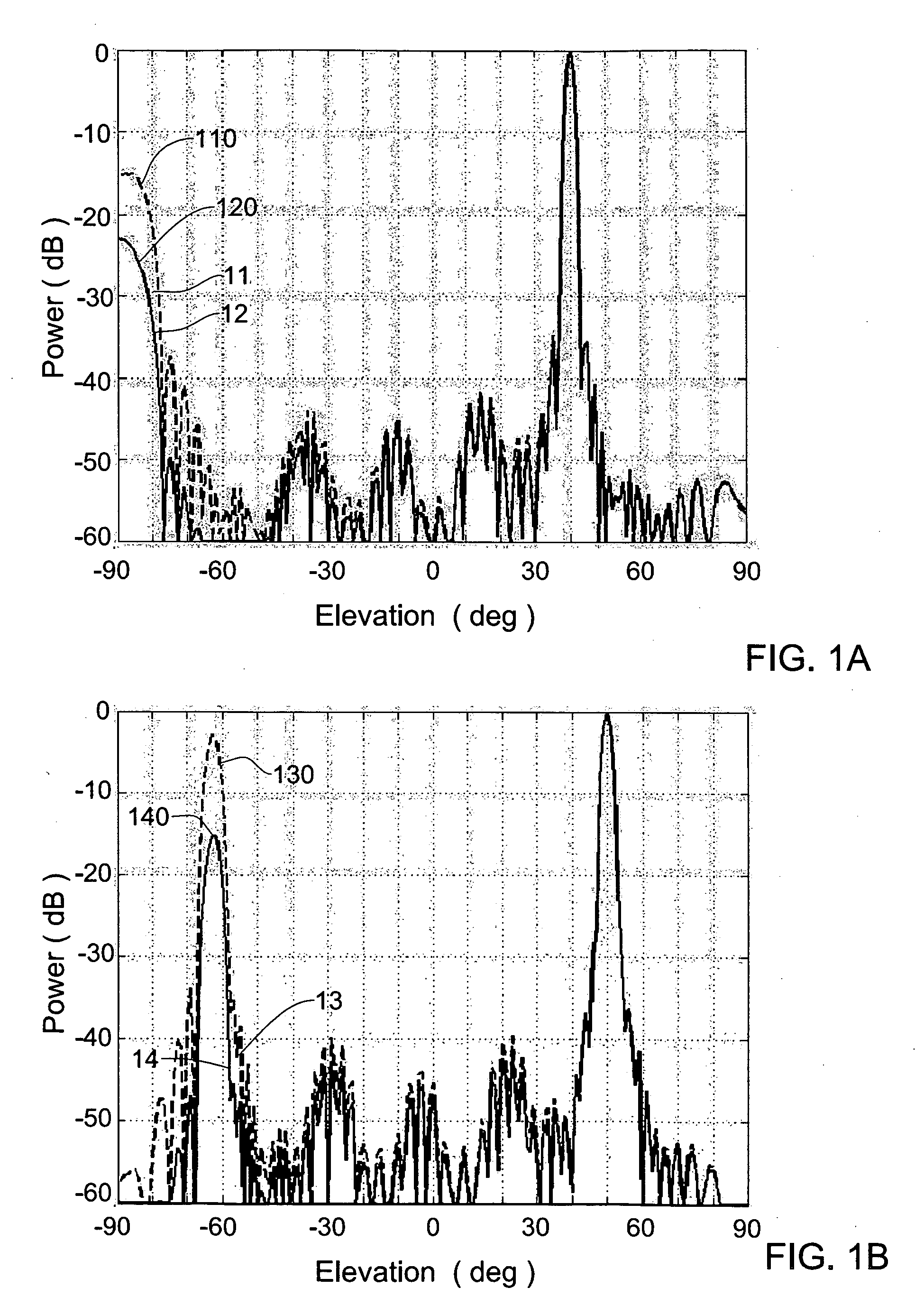
[0052] According to the phased array radiation theory, due to the array pattern multiplication property, a vector of the total radiation pattern Etot(k) of an array of identical antenna elements in the far-field approximation can be obtained by Etot(k)=F(k)A(k), where k=2πr / λ is the wave vector, r is the unit vector in the direction of a certain point in space having coordinates (R, θ, φ), λ is the wavelength; the factor F(k) is related to a...


PUM


Abstract

A method of suppressing grating lobes generated in a radiating pattern of a phased array antenna, and a patch antenna element for use in the phased array antenna are described. The phased array antenna is formed from a plurality of symmetrical patch antenna elements spaced apart at a predetermined distance from each other. Each patch antenna element is configured for producing an asymmetrical radiation pattern. The antenna element includes a conductive ground plane, a radiating patch backed by a cavity and arranged in cavity aperture, and a feed arrangement. The patch antenna element is configured such that a dimension of the radiating patch along the E-plane of the antenna element is less than the dimension of the cavity aperture by a first predetermined value selected to provide an asymmetrical radiation pattern of the patch antenna element. To provide a required degree of the asymmetry of said radiation pattern, a dimension of the radiating patch along the H-plane should be less than the dimension of the cavity aperture along said H-plane by a second predetermined value.

Description

FIELD OF THE INVENTION [0001] The present invention relates generally to directional beam forming antennas, and in particular, to a phased array antenna configuration for suppressing grating lobes. BACKGROUND OF THE INVENTION [0002] There are many applications employing antennas for transmitting and receiving electromagnetic signals in which the defining of antenna gain patterns with maximas for directional transmitting and receiving the signals is a desirable feature. One type of such antenna systems is the active transmit phased array having a plurality of individual antenna elements which are interconnected in ways designed to enable, for example, electronic steering of the radiated beams of electromagnetic energy in space, without physical movement of the whole array. The antenna elements can be distributed uniformly or non-uniformly over a prescribed surface area, and chosen to provide the desired antenna radiation characteristics. The surface may be planar or curved, in more t...

Claims


Application Information

Patent Timeline
IPC IPC(8): H01Q1/38
CPCH01Q9/0407H01Q21/065
Inventor ILUZ, ZEEVBAUER, REUVEN
Owner ELTA SYST LTD
Why Eureka
Try Eureka