Exposure apparatus, exposure method, and method for producing device

a technology of exposure apparatus and exposure method, which is applied in the direction of photomechanical treatment, printing, instruments, etc., can solve the problems of deterioration of exposure accuracy and measurement accuracy, inconvenience, and difficulty in filling the optical path space of exposure light beam,

Inactive Publication Date: 2007-06-14
NIKON CORP
View PDF25 Cites 35 Cited by
  • Summary
  • Abstract
  • Description
  • Claims
  • Application Information

AI Technical Summary

Benefits of technology

[0028] According to the tenth aspect of the present invention, it is possible to produce the device by using the exposure method which makes it possible to fill the optical path space for the exposure light beam with the liquid in a desired state.
[0029] According to the present invention, it is possible to fill the optical path space for the exposure light beam with the liquid in a desired state, and it is possible to satisfactorily perform the exposure process and the measurement process through the liquid.

Problems solved by technology

That is, it is difficult to fill the optical path space for the exposure light beam with the liquid in a desired state.
Further, there is such a possibility that the exposure accuracy and the measurement accuracy, which are to be obtained through the liquid, may be deteriorated.
For example, as the velocity of the movement of the substrate (substrate stage) is increased to be high, the following inconvenience arises.
That is, it is impossible to sufficiently fill the optical path space for the exposure light beam with the liquid, and the bubble is formed in the liquid, etc.
Further, when the velocity of the movement of the substrate (substrate stage) is increased to be high, a possibility arises such that the liquid, with which the optical path space is filled, may leak out as well.
When the liquid leaks out, for example, the corrosion and the trouble of peripheral members and equipment are caused.
As a result, it is feared that the exposure accuracy, which includes, for example, the pattern overlay accuracy on the substrate, may be deteriorated, and the various measurement accuracies, which are based on the use of, for example, the interferometer, may be deteriorated.
When the substrate, on which the liquid has remain (adhere), is unloaded from the substrate stage, it is feared that the liquid is also adhered to the transport system for holding the wetted substrate, and the damage may be expanded.
As a result, it is feared that the entire exposure apparatus may be enormously large-sized as well.

Method used


Image

  • Exposure apparatus, exposure method, and method for producing device
  • Exposure apparatus, exposure method, and method for producing device
  • Exposure apparatus, exposure method, and method for producing device

Examples


first embodiment

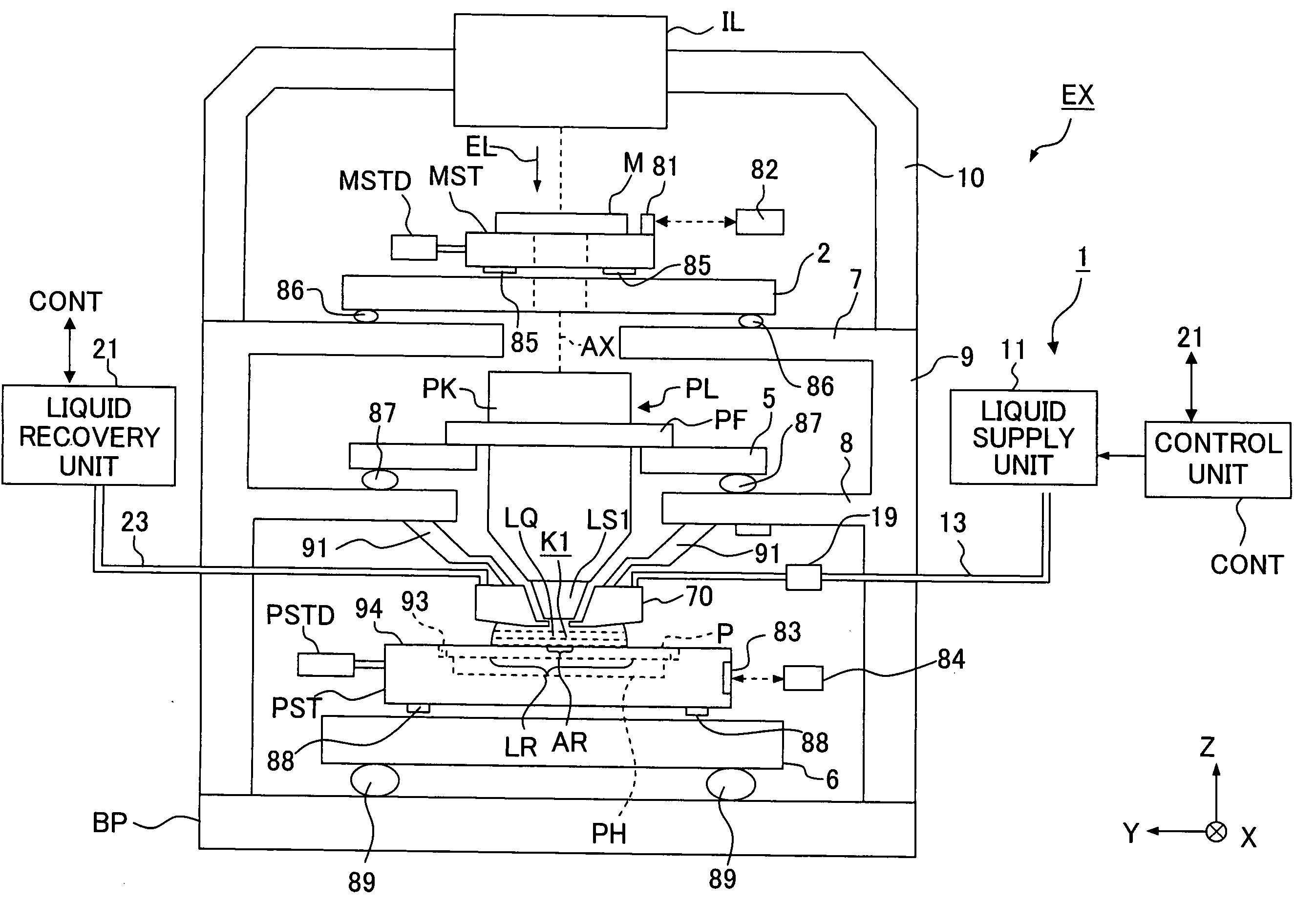
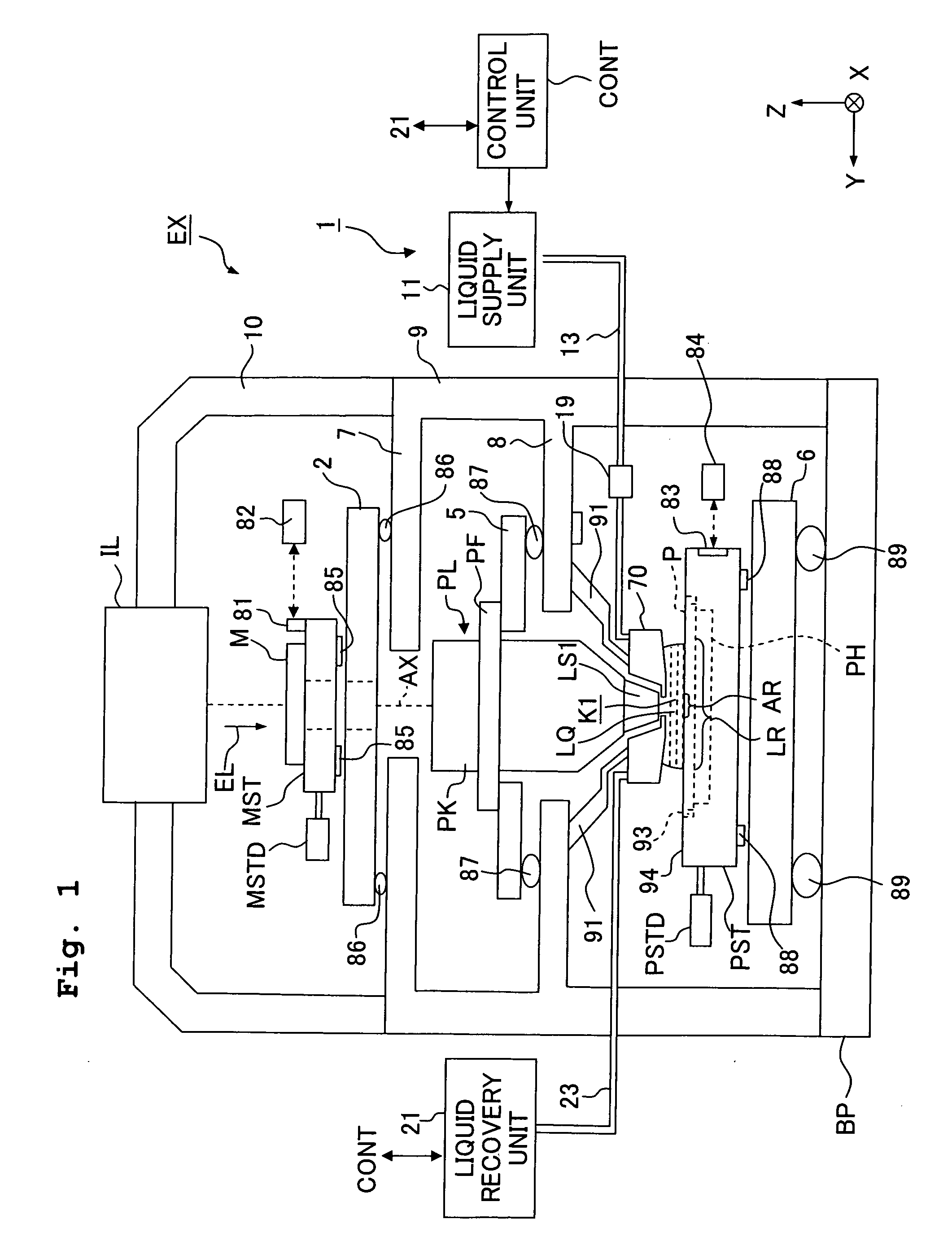
[0053]FIG. 1 shows a schematic arrangement illustrating an exposure apparatus according to a first embodiment. With reference to FIG. 1, the exposure apparatus EX includes a mask stage MST which is movable while holding a mask M, a substrate stage PST which is movable while holding a substrate P, an illumination optical system IL which illuminates, with an exposure light beam EL, the mask M held by the mask stage MST, a projection optical system PL which projects an image of a pattern of the mask M illuminated with the exposure light beam EL onto the substrate P held by the substrate stage PST, and a control unit CONT which controls the overall operation of the exposure apparatus EX.

[0054] The exposure apparatus EX of this embodiment is a liquid immersion exposure apparatus in which a liquid immersion method is applied in order that the exposure wavelength is substantially shortened to improve the resolution and the depth of focus is substantially widened. The exposure apparatus EX...

second embodiment

[0134] Next, a second embodiment will be explained with reference to FIGS. 9 to 12. In the following description, the constitutive portions, which are the same as or equivalent to those of the first embodiment described above, are designated by the same reference numerals, any explanation of which will be simplified or omitted.

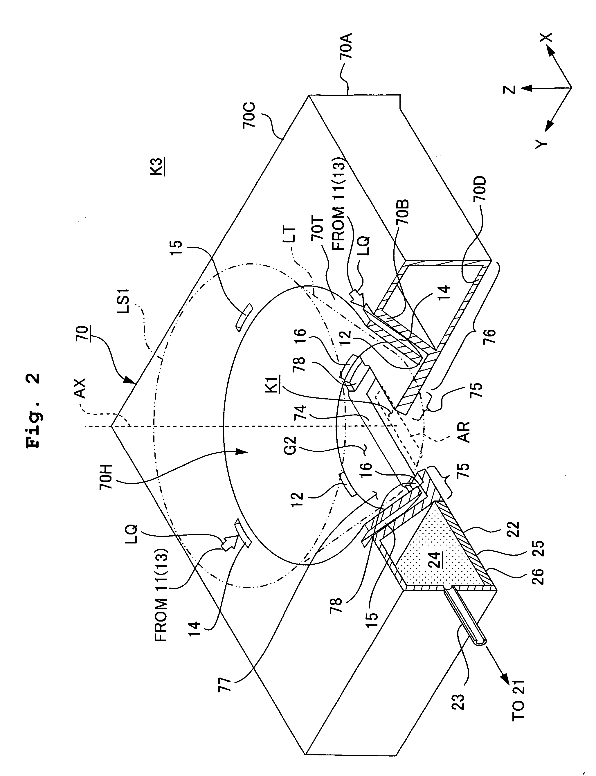
[0135]FIG. 9 shows a schematic perspective view with partial cutout, illustrating those disposed in the vicinity of a nozzle member 70 according to the second embodiment. FIG. 10 shows a perspective view illustrating the nozzle member 70 as viewed from the lower side. FIG. 11 shows a side sectional view taken in parallel to the XZ plane. FIG. 12 shows a side sectional view taken in parallel to the YZ plane.

[0136] The opening 74, through which the exposure light beam EL is allowed to pass, is formed at the central portion of the bottom plate portion 70D of the nozzle member 70. The opening 74 has a shape according to the projection area AR. The opening 74 is ...

third embodiment

[0160] Next, a third embodiment will be explained with reference to FIGS. 14 to 17. FIG. 14 shows a schematic perspective view with partial cutout, illustrating the vicinity of a nozzle member 70 according to the third embodiment. FIG. 15 shows a perspective view illustrating the nozzle member 70 as viewed from the lower side. FIG. 16 shows a side sectional view taken in parallel to the XZ plane. FIG. 17 shows a side sectional view taken in parallel to the YZ plane.

[0161] The opening 74, through which the exposure light beam EL is allowed to pass, is formed at the central portion of the bottom plate portion 70D of the nozzle member 70. The opening 74 has a shape corresponding to the projection area AR. The opening 74 is formed to have a slit-shaped form in which the X axis direction is the longitudinal direction in the same manner as in the first embodiment described above. A first land surface 75 is provided around the opening 74 on the lower surface of the nozzle member 70. The f...


PUM


Abstract

An exposure apparatus includes a first land surface which faces a surface of a substrate and which surrounds an optical path space for an exposure light beam, a second land surfaces which faces the surface of the substrate and which is provided outside the first land surface in a predetermined direction, and a recovery port which is provided to recover a liquid for filling the optical path space therewith. The first land surface is provided subsequently in parallel to the surface of the substrate. The second land surface is provided at positions separated farther from the surface of the substrate than the first land surface. The recovery port is provided outside the first land surface and the second land surface. Even when the exposure is performed while moving the substrate, the optical path space for the exposure light beam can be filled with the liquid in a desired state.

Description

CROSS-REFERENCE [0001] This application is a Continuation Application of International Application No. PCT / JP2006 / 306711 which was filed on Mar. 30, 2006 claiming the conventional priority of Japanese patent Application Nos. 2005-101485 filed on Mar. 31, 2005, and 2005-169544 filed on Jun. 9, 2005; and claiming the priority of U.S. Provisional Application No. US60 / 742,934 filed on Dec. 7, 2005.BACKGROUND OF THE INVENTION [0002] 1. Field of the Invention [0003] The present invention relates to an exposure apparatus, an exposure method, and a method for producing a device, in which a substrate is exposed through a liquid. [0004] 2. Description of the Related Art [0005] An exposure apparatus, which projects a pattern formed on a mask onto a photosensitive substrate, is used in the photolithography step as one of the steps of producing microdevices such as semiconductor devices and liquid crystal display devices. The exposure apparatus includes a mask stage which is movable while holdin...

Claims


Application Information

Patent Timeline
Patent Type & Authority Applications(United States)
IPC IPC(8): G03B27/00
CPCG03B27/00G03F7/70341
Inventor NAGASAKA, HIROYUKI
Owner NIKON CORP
Why Eureka
Try Eureka