
Method of intravascularly delivering stimulation leads into brain to stimulate the spg

a technology of electrical stimulation and brain, applied in the field of diseases, can solve the problems of additional risks, a burr hole is needed, and the technique is still quite invasiv

Active Publication Date: 2007-06-14
BOSTON SCI SCIMED INC
View PDF99 Cites 33 Cited by
  • Summary
  • Abstract
  • Description
  • Claims
  • Application Information

AI Technical Summary

Benefits of technology

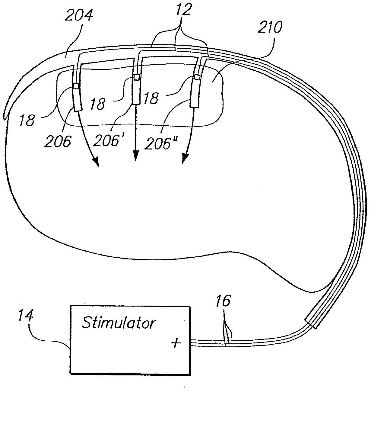
The present invention provides a method for treating neurological disorders in patients by delivering a stimulation lead through the circulatory system or ventricular system to the brain tissue that needs to be stimulated. The stimulation lead can be placed adjacent to the brain tissue or into indirect contact with it. The stimulation lead can take different forms, such as an exposed signal wire and electrode, or a catheter with a signal wire and electrode. The method can also include electrically coupling the stimulation lead to a stimulation source that can be implanted within the patient's body. The technical effect of this invention is that it provides a minimally invasive and efficient way to treat neurological disorders by delivering a stimulation lead to the brain tissue that needs to be stimulated.

Problems solved by technology

Although the current brain stimulation techniques used to treat neurological disorders have proven to be successful, such techniques are still quite invasive, requiring the cranium to be opened through at least one burr hole.
In addition, the need for a burr hole further complicates the procedure—not only requiring the additional step of accessing the patient's cranium while attempting to minimize tissue trauma, but also requiring that the burr hole be capped at the end of the procedure.
Also, additional risks are posed by the possibility that the burr hole may become infected and the routing of the stimulation or extension leads through the neck in close proximity to the jugular veins and carotid arteries.

Method used


Image

  • Method of intravascularly delivering stimulation leads into brain to stimulate the spg
  • Method of intravascularly delivering stimulation leads into brain to stimulate the spg
  • Method of intravascularly delivering stimulation leads into brain to stimulate the spg

Examples


Embodiment Construction

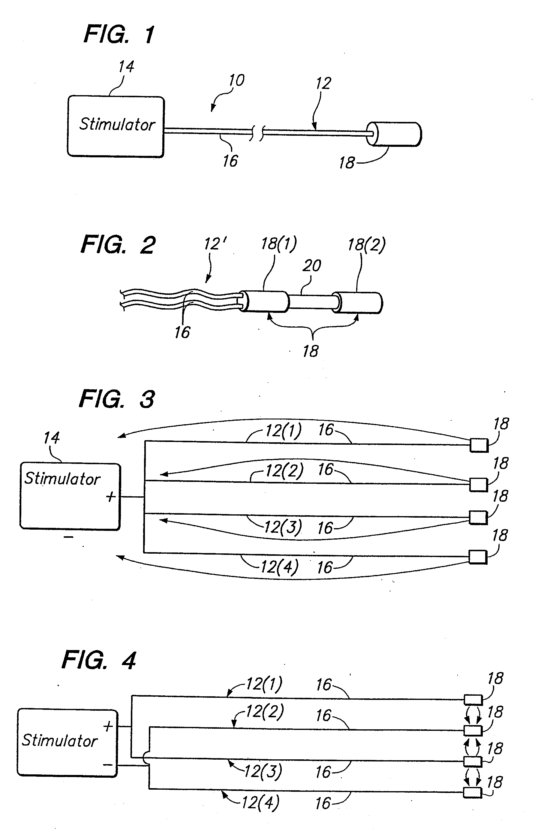
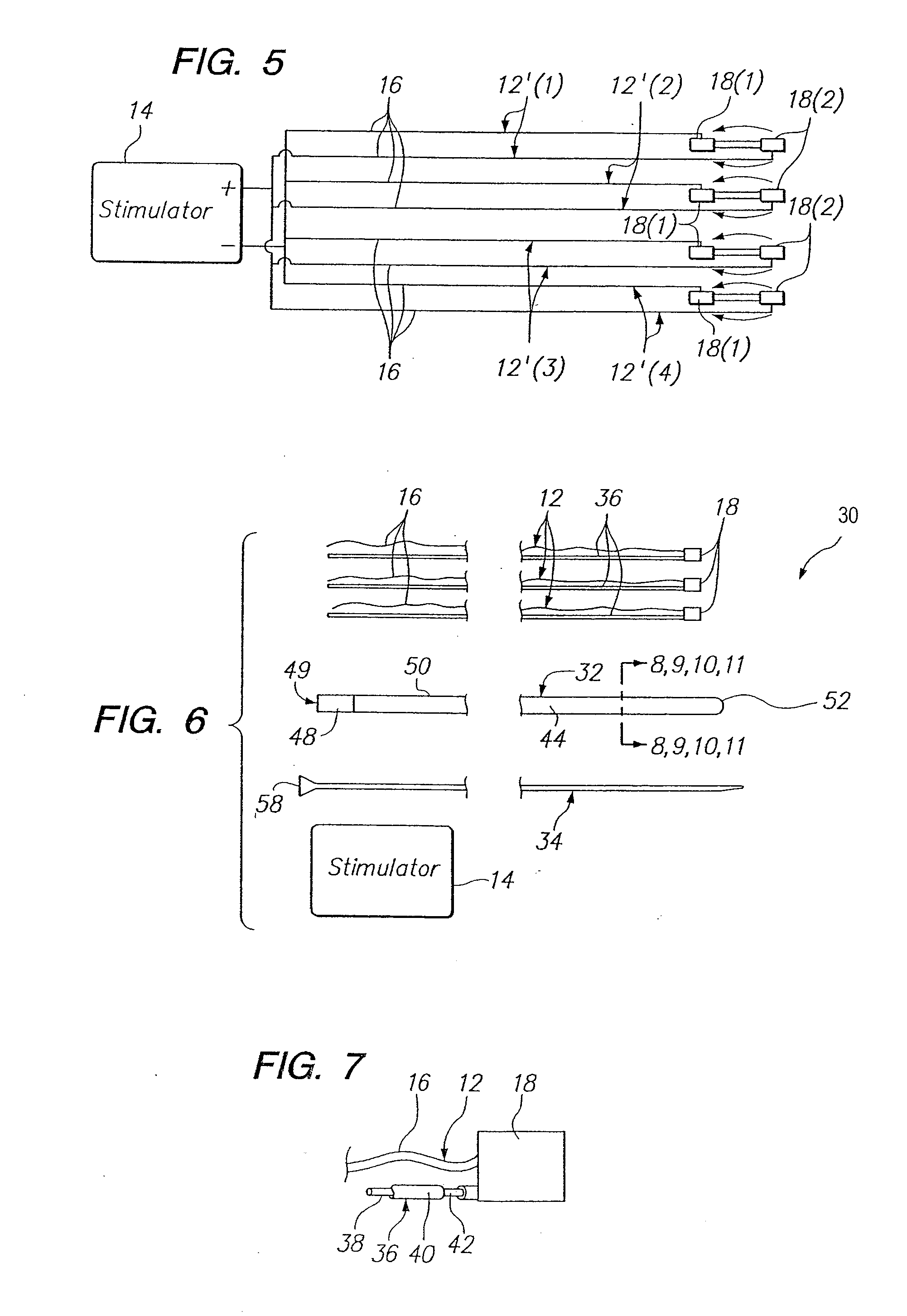
[0071] Referring now to FIG. 1, an intravascular brain stimulation system 10 constructed in accordance with one preferred embodiment of the present invention is shown. In its simplest form, the stimulation system 10 generally comprises an electrical stimulation electrode lead 12 configured to be intravascularly implanted within a selected region of a patient's brain, and an implantable electrical stimulation source 14 configured for delivering stimulation energy to the stimulation lead 12.

[0072] The stimulation electrode lead 12 comprises a flexible electrically conductive wire 16 and a single electrode 18 mounted at the distal end of the wire 16 using suitable connection means, such as soldering or welding. In the illustrated embodiment, the electrode 18 is cylindrically shaped and has a size that allows it to be delivered through a delivery catheter, as will be described in further detail below. The wire 16 comprises an electrically conductive core with an outer insulative layer....


PUM


Abstract

A method of treating a neurological disorder in a patient is provided. The method comprises intravascularly delivering a stimulation lead within the head of the patient, and placing the stimulation lead adjacent brain tissue (e.g., cortical brain tissue or deep brain tissue), the stimulation of which will treat the neurological disorder. The stimulation lead can be placed into indirect contact with the brain tissue (e.g., through a blood vessel) or indirect contact with the brain tissue (e.g., when placed within the ventricular cavity or by being introduced through an exit point within a vessel wall). Optionally, the method comprises implanting a source of stimulation within the patient's body, and then electrically coupling the proximal end of the stimulation lead, which conveniently extends from the access point within the circulatory system, to the implanted stimulation source. Using the stimulation lead, the brain tissue can then be stimulated in order to treat the neurological disorder.

Description

RELATED APPLICATIONS [0001] This application is related to copending U.S. patent application Ser. No. 10 / ______ (attorney docket number 2024730-7037252001), filed on the same date, and expressly incorporated herein by reference.FIELD OF THE INVENTION [0002] The invention relates to the treatment of diseases, and in particular, the therapeutic treatment of tissue using electrical stimulation. BACKGROUND OF THE INVENTION [0003] It is known to treat neurodegenerative diseases, such as Alzheimer's Disease, Parkinson's Disease, Tremor, and Epilepsy, and ischemia of the brain, such as stroke, by electrically stimulating selected portions of the brain. Currently, this is accomplished by first drilling a burr hole through the patient's cranium in order to gain access to the brain tissue. A stimulation lead, and in particular, a lead with multiple electrodes extending along its length, is then introduced through one or more burr holes into contact with the selected brain tissue. In a deep br...

Claims


Application Information

Patent Timeline
Patent Type & Authority Applications(United States)
IPC IPC(8): A61N1/36A61N1/05A61N1/18
CPCA61N1/0529A61N1/0531A61N1/0534
Inventor WALLACE, MICHAEL P.GARABEDIAN, ROBERT J.ABRAMS, ROBERT M.
Owner BOSTON SCI SCIMED INC
Learn More