Granular biomass burning heating system

a heating system and biomass technology, applied in the field of granular biomass burning heating system, can solve the problems of back burning of biomass furnaces, incomplete burning of biomass fuel, and problems associated with controls in grain burning heating systems, so as to reduce lag time, increase unit efficiency, and achieve maximum heating results

Inactive Publication Date: 2007-06-21
STERR KEVIN K
View PDF64 Cites 43 Cited by
  • Summary
  • Abstract
  • Description
  • Claims
  • Application Information

AI Technical Summary

Benefits of technology

[0012] The invention may include a smart thermostat and a variable speed air inducer fan. The unit may utilize the smart thermostat to determine when and how long to use the high burn status before selecting the intermediate burn, low burn, burnout, or wash down status. This allows the unit to adjust itself to use the minimum amount of fuel to achieve maximum heating results. The computer chooses the heat status required for to further increase efficiency of the unit. The computer also decreases the lag time between the call for heat and actual heat. This units starts at high burn to generate maximum heat initially and through the process the unit turns down heat output when necessary to limit wasted heat.

Problems solved by technology

Further, some known biomass fuel furnaces have problems with incomplete burning of the fuel.
One of the problems associated with some grain burning heating systems is back burning.
Some known biomass furnaces have problems associated with the controls.
For example, the heat of the furnace can be difficult to control.
Additional problems included fly ash build up in previous furnaces.
Additionally, incomplete combustion can clog the system by creating clinkers, or hardened lumps of unburned material, and can also decrease efficiency.

Method used


Image

  • Granular biomass burning heating system
  • Granular biomass burning heating system
  • Granular biomass burning heating system

Examples


Embodiment Construction

[0032] Although the disclosure hereof is detailed and exact to enable those skilled in the art to practice the invention, the physical embodiments herein disclosed merely exemplify the invention which may be embodied in other specific structures. While the preferred embodiment has been described, the details may be changed without departing from the invention, which is defined by the claims.

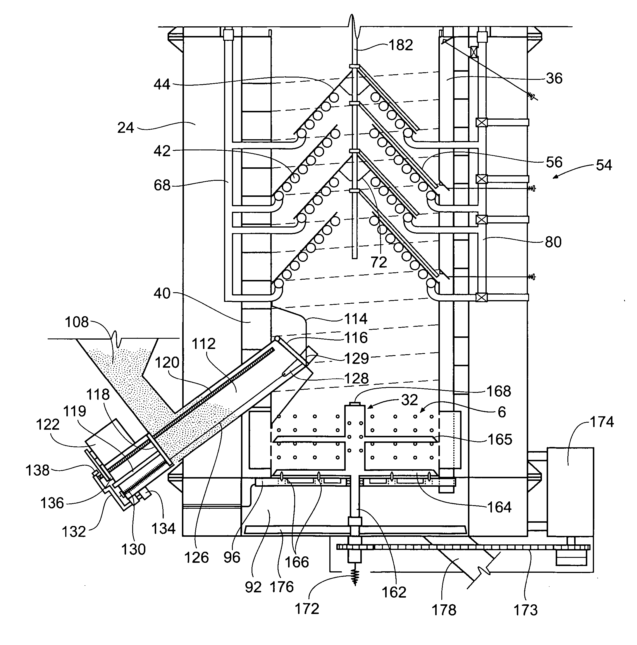
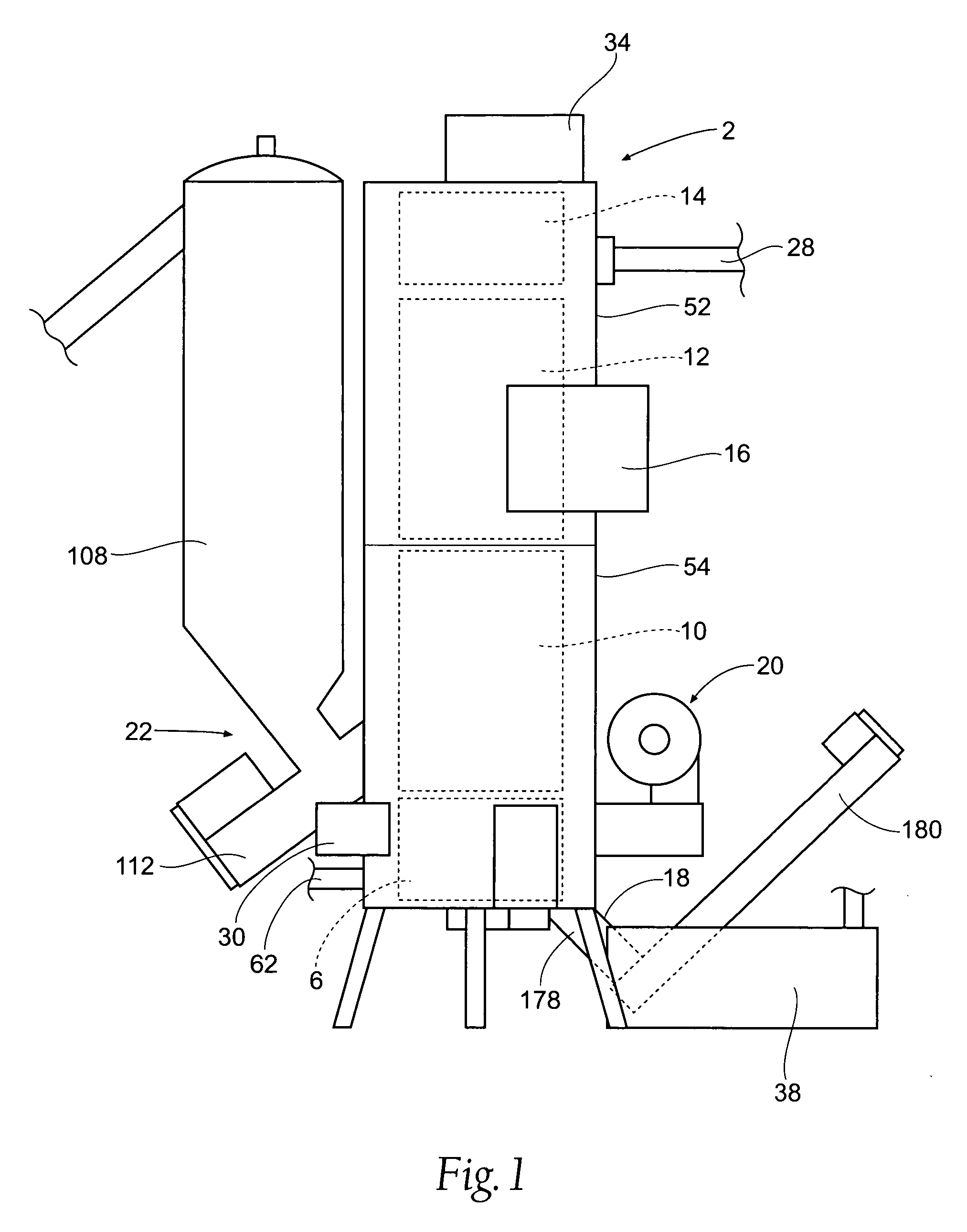
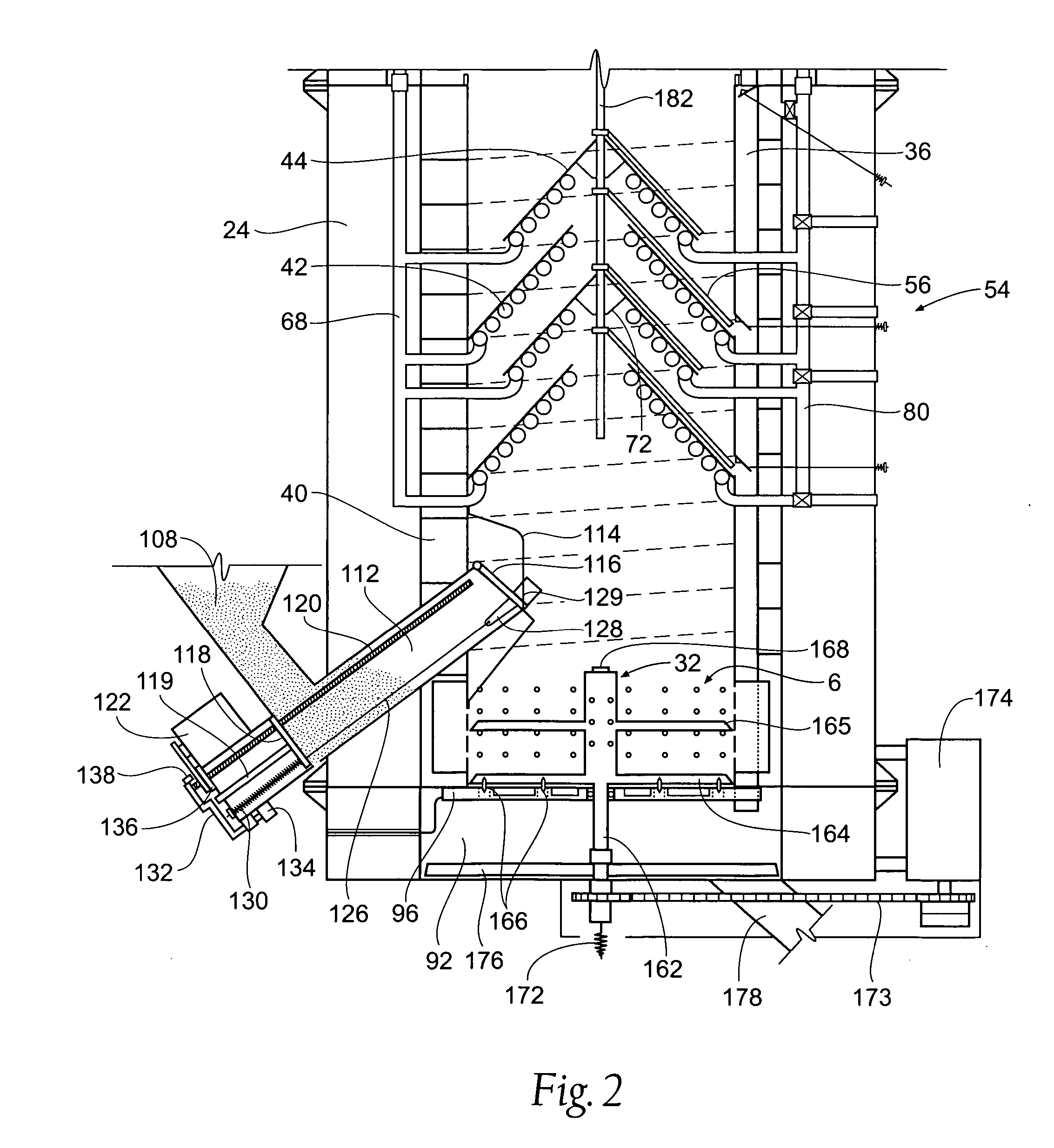
[0033]FIG. 1 shows the furnace 2 of the presenting invention in a very simplified form. The furnace 2 has a lower portion 54 and an upper portion 52. Within the lower portion 54 of the furnace 2 is a burn pot 6 and a first stage heat exchanger 10. A second stage heat exchanger 12 lies in both the lower portion 54 and the upper portion 52 of the furnace. The upper portion 52 of the furnace 2 also includes a third stage heat exchanger 14. The furnace 2 is preferably controlled by a computer 16. A plurality of sensors (shown in FIG. 7) are located throughout the furnace 2 to measure conditions. The...


PUM


Abstract

A granular biomass burning furnace for use with any appropriate granular biomass, such as grains, cherry pits, etc. The furnace includes a three stage heat exchanger, a fuel injector, a fuel stirrer, an ash ejector, a wash down system, a three stage air inducer, a fuel igniter, and supporting components. The unit includes a computer controller which controls all aspects of the operation of the unit based on information from sensors located throughout the unit. The unit includes a smart logic thermal controller to adjust the output heat of the unit via a variable speed air inducer. The three stage heat exchanger system includes a spiral water jacket surrounding the burn pot, a plurality of heat exchanger baffles in the unit, and a fine finned heat exchanger at the top of the unit. The air inducer provides air to the burn pot from three directions to promote complete combustion.

Description

BACKGROUND OF THE INVENTION [0001] The present invention relates to a granular biomass burning heating system. Any type of granular biomass can be used as fuel. Grains, such as corn and wheat, have become popular fuel sources for furnaces and stoves. Various stoves and furnaces of a type to burn such materials are known. [0002] In any type of solid fuel burning system, regardless of the type of fuel being used, it is desired to increase the efficiency of the system so that the amount of heat produced and utilized by the system is relatively high. It is further desired to decrease the lag time between unit start up and when heat is evident to the user. Further, some known biomass fuel furnaces have problems with incomplete burning of the fuel. Therefore it is desirable to provide a biomass furnace which provides for complete burning of the fuel. [0003] One of the problems associated with some grain burning heating systems is back burning. Many granular biomass burning heating systems...

Claims


Application Information

Patent Timeline
Patent Type & Authority Applications(United States)
IPC IPC(8): F23J1/00F23B30/00F23B90/00F27D27/00
CPCF23B30/00F23B40/08F24H2230/00F23N5/00F24H1/43F23N3/082
Inventor STERR, KEVIN K.
Owner STERR KEVIN K
Why Eureka
Try Eureka