Die casting in investment mold

a technology of investment casting and mold cavity, which is applied in the field of investment casting of metals and alloys, can solve the problems of low casting yield, low cost and low yield of investment casting of complex shaped components of such titanium based materials, and difficult filling of thin wall mold cavity regions having a thickness of less than 0.050-0.060 inch,

Inactive Publication Date: 2007-06-21
HOWMET CORPORATION
View PDF3 Cites 44 Cited by
  • Summary
  • Abstract
  • Description
  • Claims
  • Application Information

AI Technical Summary

Benefits of technology

[0014] Moreover, the invention can be used to cast complex investment molds having backlocks, undercuts, or other features that can not be cast using metal dies. Practice of the invention permits complex mold geometries to be cast, without the need for significant chemical and / or mechanical rework of the die cast component.

Problems solved by technology

Although commonly used, investment casting of complex shaped components of such titanium based materials can be characterized by relatively high costs and low yields.
Low casting yields are attributable to several factors, in particular inadequate filling of certain mold cavity regions such as especially thin wall mold cavity regions.
For example, filling of thin wall mold cavity regions having a thickness of less that 0.050-0.060 inch with a titanium alloy or titanium aluminide melt is difficult due to melt fluidity, low superheat, and out-gassing problems.
However, such an approach is disadvantageous in that the molten titanium alloy or titanium aluminide can react with the mold at such high temperatures to form deleterious phases on the surface of the castings produced in such shell molds.
Moreover, it is oftentimes necessary to increase the thickness of one or more thin wall mold cavity regions when the mold is being made in order to subsequently achieve satisfactory mold filling during casting.
Drawbacks of using metal die casting molds include the high cost of the metal dies and the presence of die parting line between the metal dies, which parting line sometimes limits the complexity of the die cavity and thus the casting that can be die cast.
A further drawback of using metal dies when die casting titanium aluminide material is the generation of cracking in the casting as a result of rapid solidification of the melt in the metal mold.

Method used


Image

  • Die casting in investment mold
  • Die casting in investment mold
  • Die casting in investment mold

Examples


example 1

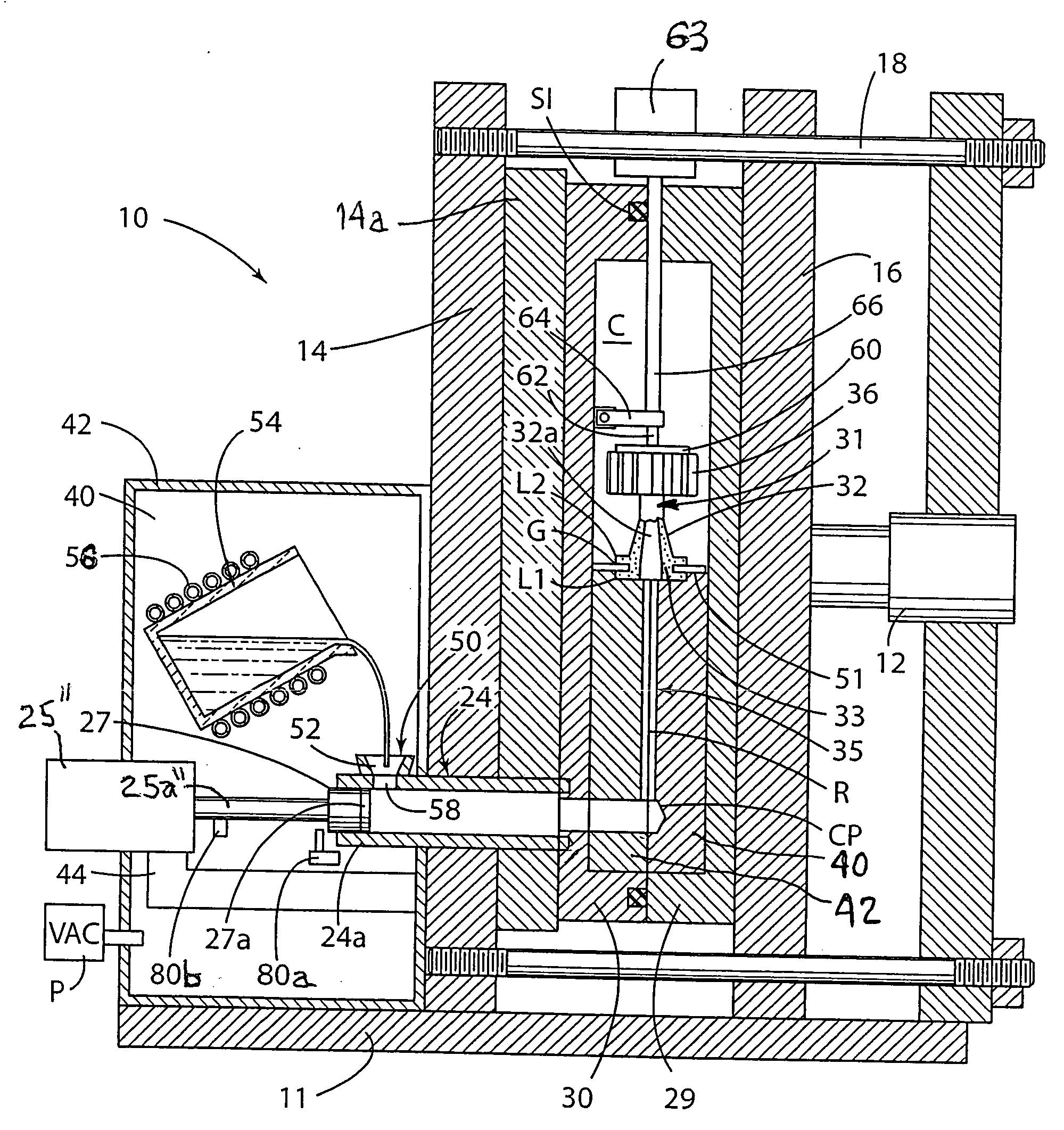
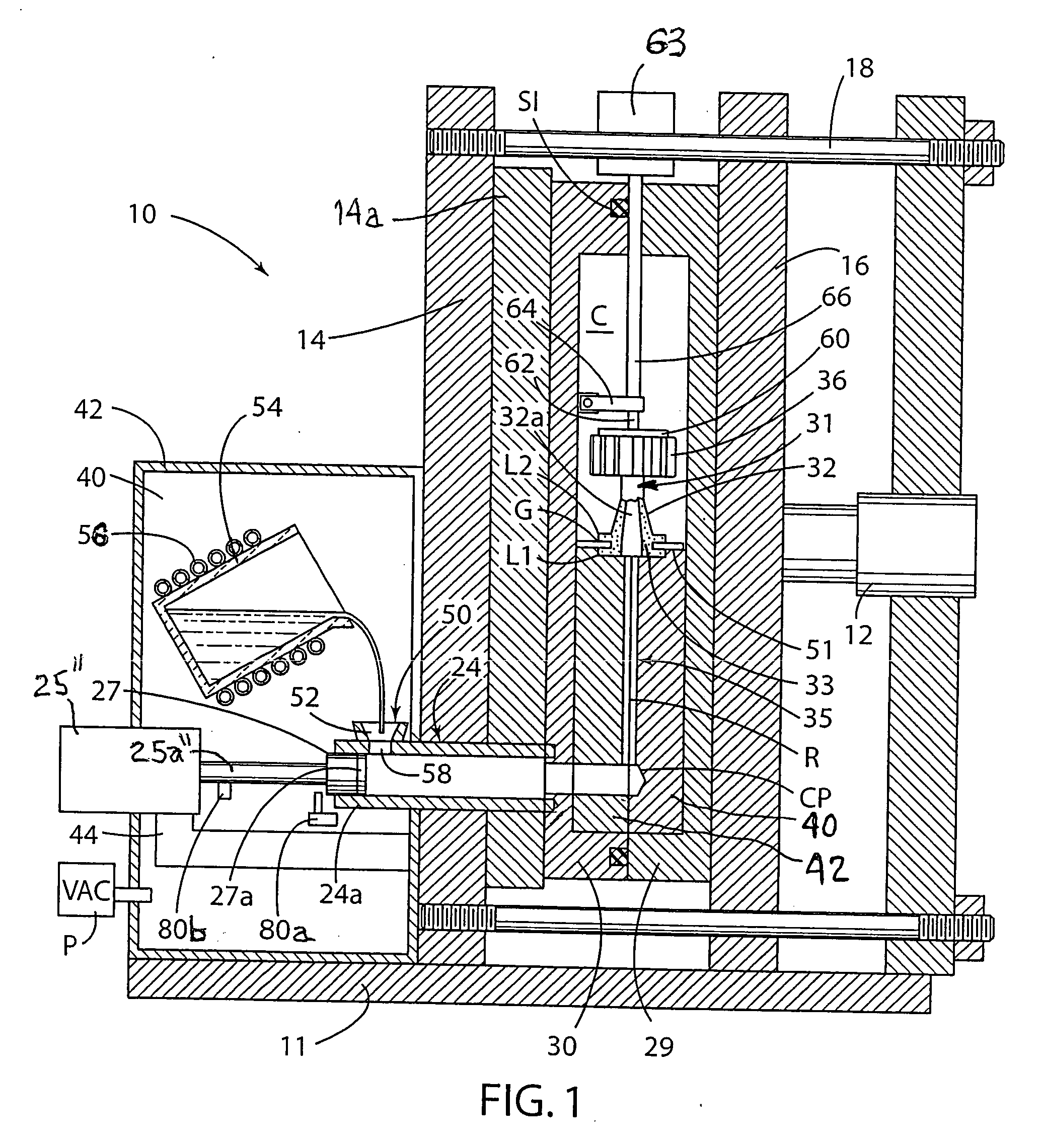
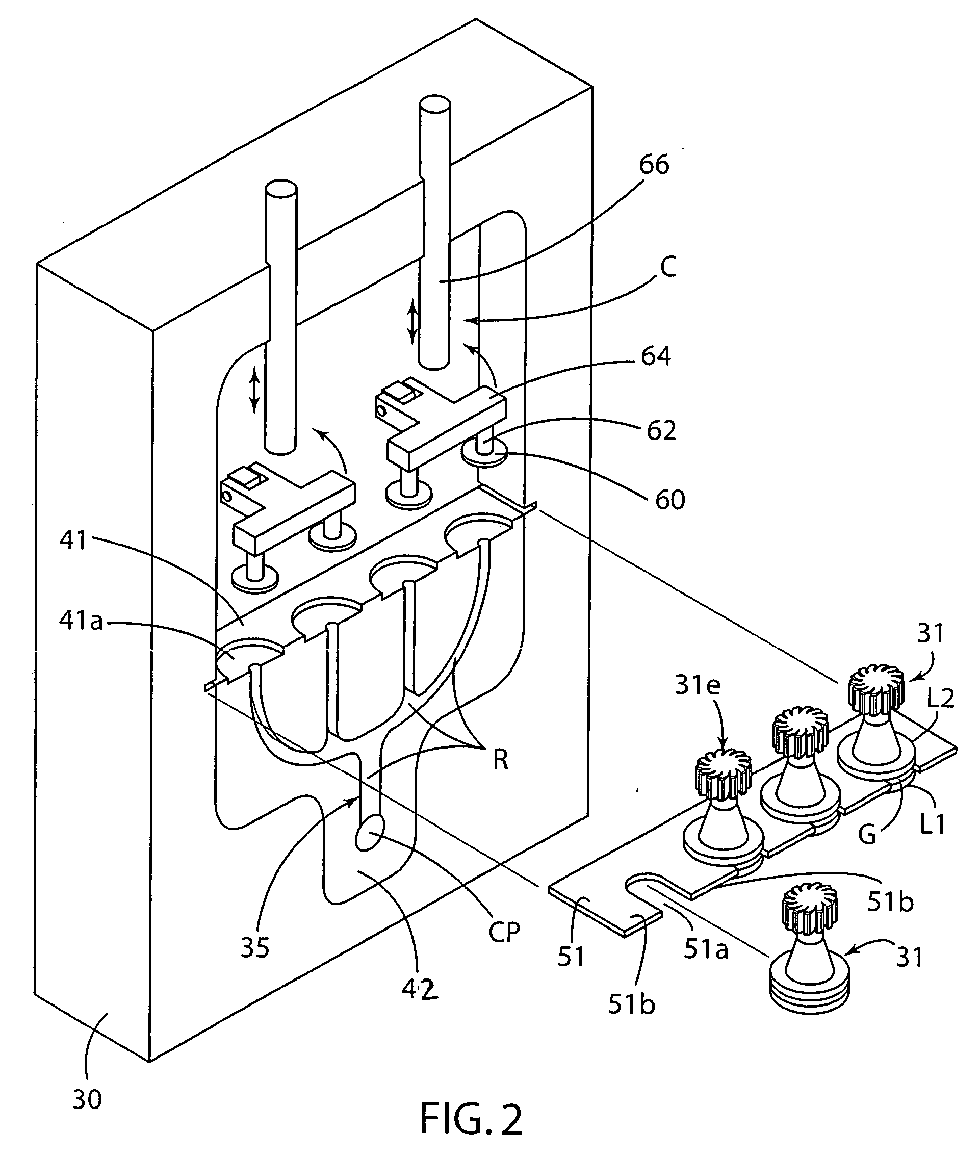
[0078] Turbocharger wheels have been successfully die cast of titanium and titanium aluminide (TiAl) alloys in conventional lost wax investment shell molds 31 by practice of the invention. In general, the turbocharger wheels were made using casting parameters in the following ranges: melt injection pressure settings: 400-1800 psi, melt injection velocities (plunger speed): 10-120 in / sec, melt superheat: 0 to 75 degrees F., mold preheat: room temperature to 600 degrees F., lost wax investment shell mold wall thickness: 0.20 to 1.0 inch, shot sleeve length and diameter: 17.38 inches and 2.80 inches; and limit switch 80a set to dump plunger fluid pressure when the plunger 27 is about 0.75 inch from its final injection position.

[0079] Although the mold 31 is illustrated above for making cast turbocharger wheels, the invention is not so limited and can practiced to make other components that include, but are not limited to, internal combustion engine valves, automotive or truck turbocha...


PUM

PropertyMeasurementUnit
thicknessaaaaaaaaaa
thicknessaaaaaaaaaa
thicknessaaaaaaaaaa

Abstract

Method and apparatus for casting a metallic material involves the steps of providing a non-metallic mold in a mold-receiving chamber disposed in at least one of relatively movable first and second members, communicating a mold cavity in the mold to a gating passage disposed in at least one of the first and second metallic members, communicating the gating passage to a shot sleeve, and flowing metallic material from the shot sleeve to the gating passage and into the non-metallic mold.

Description

FIELD OF THE INVENTION [0001] The present invention relates to casting of metals and alloys and, more particularly, to casting of metals, alloys, and intermetallics under pressure in a non-metallic investment mold. BACKGROUND OF THE INVENTION [0002] Titanium based alloys (e.g. Ti-6Al-4V) and intermetallics (e.g. TiAl) are used as cast components in the aerospace industry. Many such cast components are made by the well known gravity investment casting process wherein an appropriate melt is cast into a preheated ceramic investment shell mold formed by the lost wax process. [0003] Although commonly used, investment casting of complex shaped components of such titanium based materials can be characterized by relatively high costs and low yields. Low casting yields are attributable to several factors, in particular inadequate filling of certain mold cavity regions such as especially thin wall mold cavity regions. For example, filling of thin wall mold cavity regions having a thickness of...

Claims


Application Information

Patent Timeline
Patent Type & Authority Applications(United States)
IPC IPC(8): B22D17/08
CPCB22C9/04B22C9/082B22C9/28B22D17/10B22D17/2209B22D21/005B22D17/203
Inventor VOGT, RUSSELL G.LEE, DAVID S.WOLTER, GEORGE W.ERVIN, LEONARD L.
Owner HOWMET CORPORATION
Why Eureka
Try Eureka