Embedded nanotube array sensor and method of making a nanotube polymer composite

a technology of nanotube array and nanotubes, applied in the direction of instruments, conductors, electrochemical variables of materials, etc., can solve the problem of significant aircraft downtim

Active Publication Date: 2007-06-21
RENESSELAER POLYTECHNIC INST
View PDF19 Cites 88 Cited by
  • Summary
  • Abstract
  • Description
  • Claims
  • Application Information

AI Technical Summary

Problems solved by technology

Currently, most of these inspections are time consuming, ex

Method used


Image

  • Embedded nanotube array sensor and method of making a nanotube polymer composite
  • Embedded nanotube array sensor and method of making a nanotube polymer composite
  • Embedded nanotube array sensor and method of making a nanotube polymer composite

Examples


first embodiment

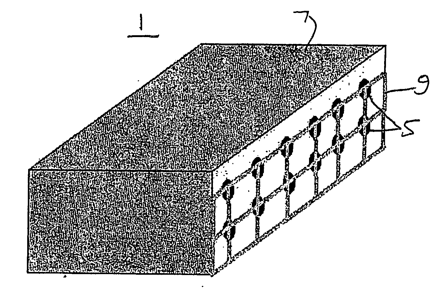
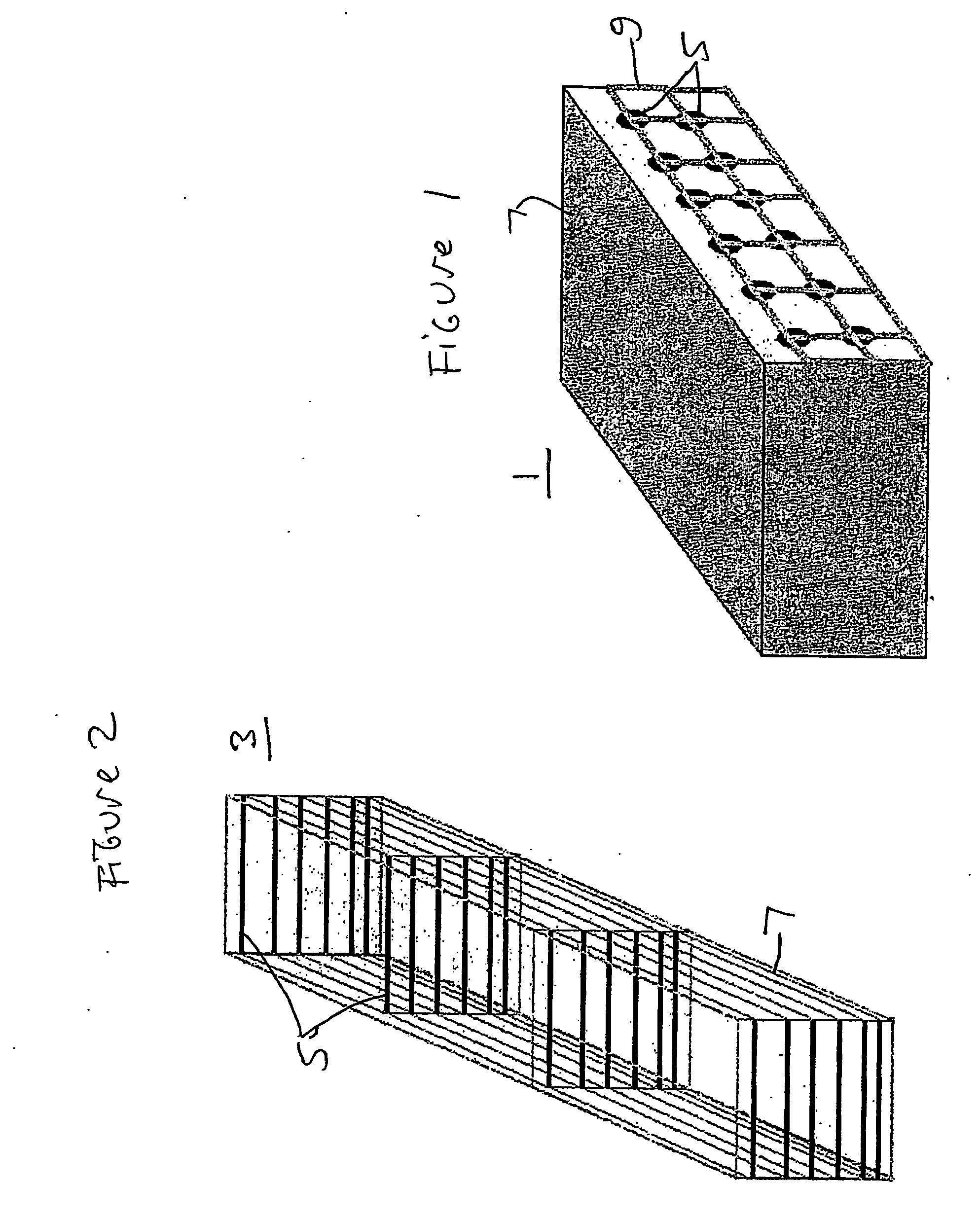
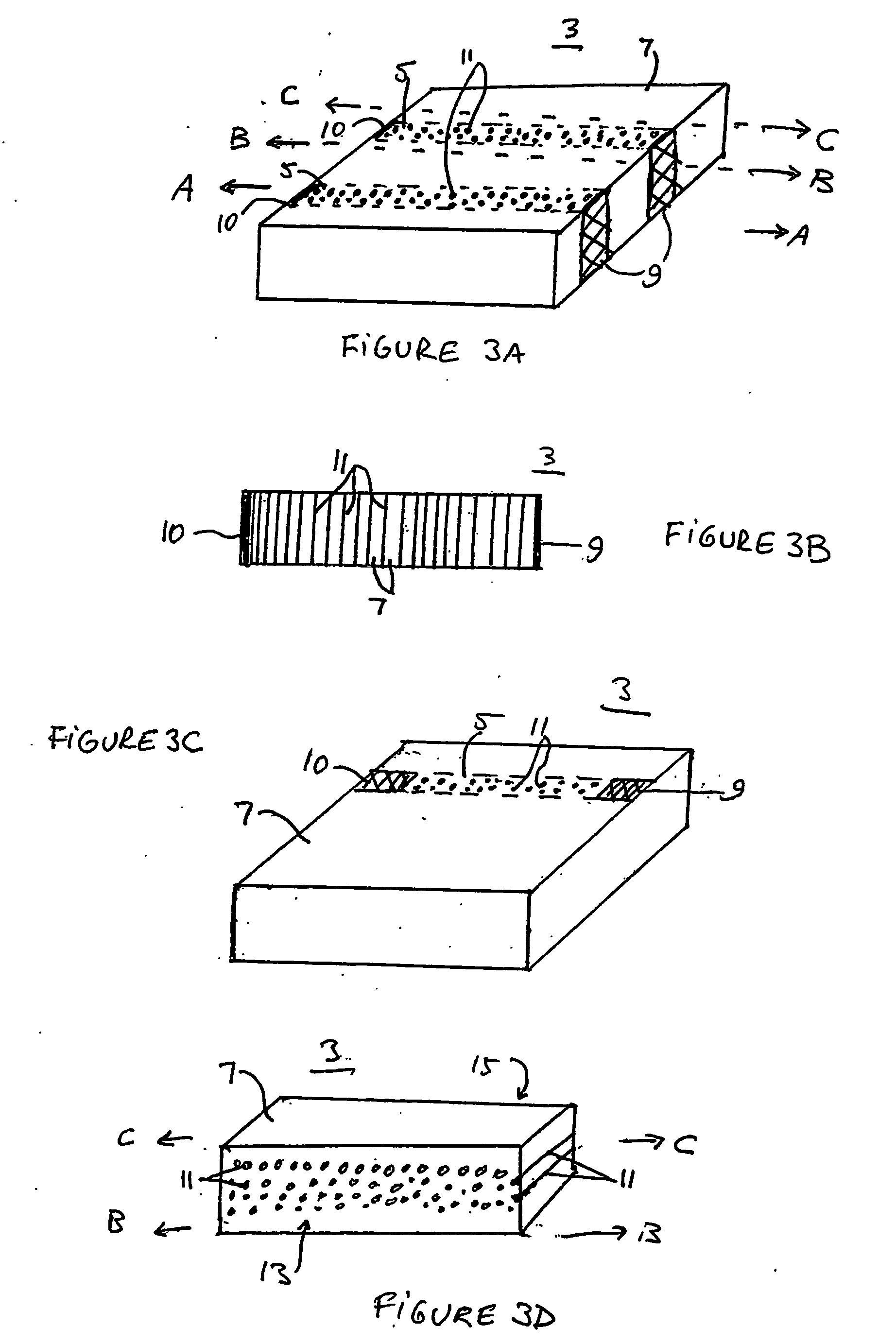
[0014] A sensor system 1 of the present invention is shown in FIG. 1. The sensor system 1 includes a nanosensor 3 shown in FIGS. 1 and 2. The nanosensor comprises at least one conductive channel and preferably a plurality of conductive channels 5. Each conductive channel 5 comprises an array of substantially aligned carbon nanotubes or carbon nanofibers embedded in a matrix material 7. The term carbon nanotubes includes multiwalled and singlewalled carbon nanotubes. Preferably, the carbon nanotubes have diameters less than 1 micron and lengths greater than 1 micron. The term nanofibers includes carbon fibers other than nanotubes having a diameter less than 100 nm and which can carry current and / or be affected by changes in thermal environments.

[0015] In other words, a plurality of conductive nanotubes or nanofibers that are arranged close together in a shape of a channel in the matrix material 7 form the conductive channels 5. While the channels 5 are preferably linear in shape, the...

second embodiment

[0041] In the invention, the nanotube (or nanofiber) polymer composite material is produced by a peel apart method. While this method may be used to form the composite nanosensor 3 or antenna described above, it can also be used to form other nanotube / polymer composite devices, such as flat panel displays (i.e., plasma displays where the nanotubes arranged in predetermined positions are used as field emission electrodes), electronic devices, quantum wires, composite structural material and actuators. A peel apart method of forming the composite material is described, for example, in Emer Lahiff, et al., Nano Letters, vol. 3, no. 10 (Sep. 13, 2003) 1333-1337, incorporated herein by reference in its entirety.

[0042] The method of malting a carbon nanotube composite material according to the second embodiment includes providing an array of carbon nanotubes on a first surface of a substrate, where the carbon nanotubes in the array are located in a predetermined pattern, depositing a flow...


PUM


Abstract

A method of producing polymer/nanotube composites where the density and position of the nanotubes (11) within the composite ca be controlled. Carbon nanotubes (11) are grown from organometallic micropatterns. These periodic nanotube arrays are then incorporated into a polymer matrix (7) by deposing a curable polymer film on the as-grown tubes. This controlled method of producing free-standing nanotube/polymer composite films may be used to form nanosensor (3) which provide information regarding a physical condition of a material (20), such as an airplane chassis or wing, in contact with the nanosensor (3).

Description

CROSS-REFERENCE TO RELATED APPLICATIONS [0001] This application claims priority to U.S. Provisional Application Ser. No. 60 / 431,834, filed Dec. 9, 2002, the disclosure of which is incorporated by reference herein in its entirety.FIELD OF THE INVENTION [0002] The present invention is generally directed to carbon nanotube devices and methods of making thereof and specifically to carbon nanotube sensors. BACKGROUND OF THE INVENTION [0003] Polymer matrix composites are used in a variety of structural applications in the aerospace industry for numerous reasons including overall weight savings and improved stability and durability. Breakthroughs in nanotechnology, more specifically, nanocomposites have significantly reduced weight and cost of these materials while enhancing other features beneficial to both military and commercial aircraft. Routine nondestructive inspections take place at periodic intervals to ensure safety of flight. These mandated inspections focus on damage caused by i...

Claims


Application Information

Patent Timeline
IPC IPC(8): G01N27/26H01B1/04H01Q1/36H01Q1/00B05D5/12G01L1/00G01M5/00G01N27/20
CPCB82Y15/00B82Y30/00G01L1/005G01L1/20G01M5/0033G01M5/0083H01B1/24H01Q1/28H01Q1/38Y10S977/953Y10S977/956
Inventor AJAYAN, PULICKEL
Owner RENESSELAER POLYTECHNIC INST
Why Eureka
Try Eureka