Control circuit and control method for DC-DC converter

Inactive Publication Date: 2007-06-21
MONTEREY RES LLC
View PDF1 Cites 13 Cited by
  • Summary
  • Abstract
  • Description
  • Claims
  • Application Information

AI Technical Summary

Benefits of technology

[0014] On the other hand, in a case where the detection signal is retarded more than the phase reference signal, it is determined that the period of the detection signal is longer than that of the phase reference signal. Accordingly, the delay circuit, after an amount of retardation time that has been decreased correspondingly to the amount of phase delayed is added to the transition signal, outputs the transition signal to the flip-flop. If the amount of retardation time is decreased, the time duration in which the flip-flop is in the second state is shortened. In case of the fixed on-time duration type DC-DC converter, if the second state becomes short, the amount of increase in the output voltage lesses. For this reason, the period of the detection signal becomes short. Also, in case of the fixed off-time duration type DC-DC converter, if the second state is short, the amount of decrease in the output voltage lessens. For this reason, the period of the detection signal becomes short.
[0015] As a result of the above-described operation, the feedback control for adjusting the period of the detection signal is performed according to the phase difference between the detection signal and the phase reference signal. As a result of this, it is possible to cause a coincidence of the period

Problems solved by technology

Accordingly, there is a possibility that when operating a plurality of DC-DC converters, owing to the difference between the operating frequencies, audible noise will occur due to the difference between the switching frequencies.
Therefore, this technique involves a problem.
Also, wh

Method used


Image

  • Control circuit and control method for DC-DC converter
  • Control circuit and control method for DC-DC converter
  • Control circuit and control method for DC-DC converter

Examples


Embodiment Construction

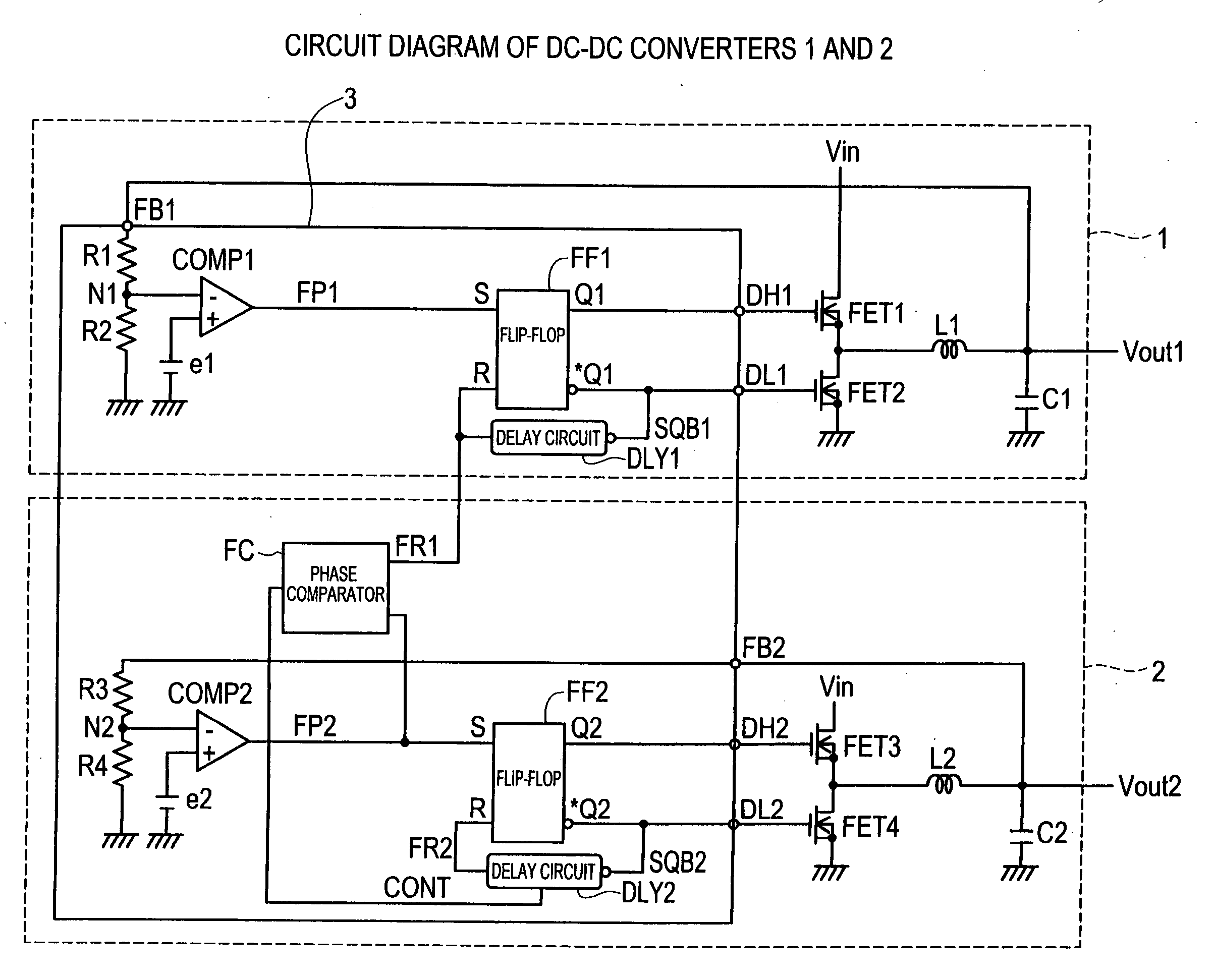
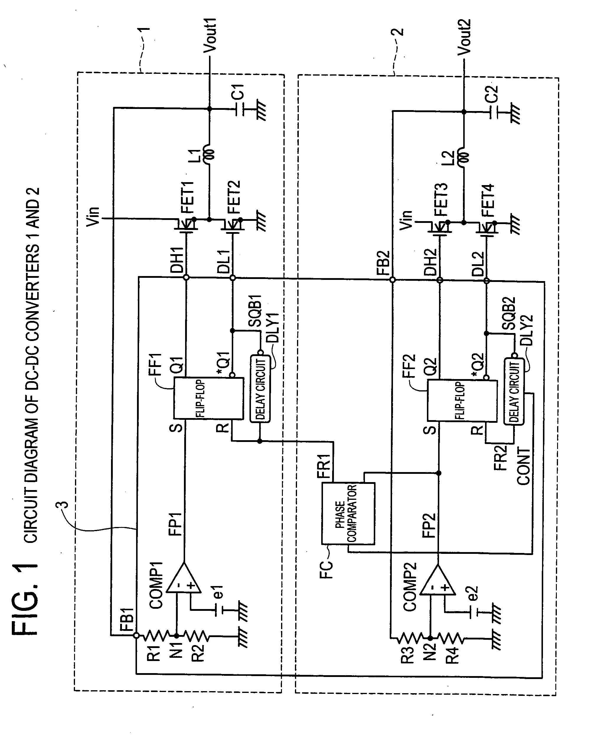
[0028]FIG. 1 is a circuit diagram of comparator type DC-DC converters 1 and 2 according to the present invention. The DC-DC converters 1 and 2 have a control part 3 that is common to each converter. First, the construction of the DC-DC converter 1 will be explained. In FIG. 1, to an input terminal of a transistor FET 1 that is a switching element, there is connected an input voltage Vin, and, to an output terminal of the transistor FET 1, there is connected an input terminal of a choke coil L1. From an output terminal of the choke coil L1, there is output an output voltage Vout1. Also, to a control terminal of the transistor FET1, there is connected an output terminal DH1 of the control part 3. An input terminal of a transistor FET2 which is a synchronous commutation switch circuit is earthed, and an output terminal thereof is connected to the input terminal of the choke coil L1. Also, to the control terminal of the transistor FET2 there is connected an output terminal DL1 of the co...


PUM


Abstract

Disclosed are a control circuit and control method for a comparator-controlled type DC-DC converter that can prevent the generation of audible noise due to the difference between relevant switching frequencies and prevent the increase in the input power source ripple voltage. A phase comparator FC outputs a compared-result signal CONT in correspondence with the phase difference between an output signal FP2 and a delay signal FR1. A delay circuit DLY2 performs a feedback control for adjusting the amount of retardation time in correspondence with the compared-result signal CONT. And, the delay circuit DLY2 outputs a delay signal FR2 after the passage of a prescribed amount of retardation time from the time when the falling edge of an output signal SQB2 has been input. At a time t16 that is after the passage of a prescribed amount of time, there is obtained a time delay DT2b that causes the period TT1 of the delay signal FR1 and the period TT2b of the output signal FP2 to coincide with each other and that makes zero the phase difference between the delay signal FR1 and the output signal FP2.

Description

CROSS-REFERENCE TO RELATED APPLICATIONS [0001] This application is based upon and claims the benefit of priority from each of the prior Japanese Patent Application No. 2005-367132 filed on Dec. 20, 2005, the entire contents of which are incorporated herein by reference. BACKGROUND OF THE INVENTION [0002] 1. Field of the Invention [0003] The present invention relates to a control circuit and control method for comparator-controlled type DC-DC converters and, more particularly, to a switching control method of the main switching transistors and a control method of operating frequencies. [0004] 2. Description of the Related Art [0005] There is a comparator-controlled PFM type DC-DC converter, in which, as a control system capable of making a high-speed response to a rapid change in the level of load, the output voltage of the DC-DC converter is compared with a reference voltage to thereby make on / off control of the main switching transistors. [0006] Incidentally, as the above-described...

Claims


Application Information

Patent Timeline
IPC IPC(8): G05F1/00
CPCH02M3/158H02M2001/008H02M1/008
Inventor HASEGAWA, MORIHITO
Owner MONTEREY RES LLC
Why Eureka
Try Eureka