Non-woven textile microwave antennas and components

a technology of microwave antennas and components, applied in the field of microstrip patch or slot antennas, can solve the problems of not being flexible and achieve the effects of increasing separation, not being flexible, and adding weight to the antennas

Inactive Publication Date: 2007-06-21
APPLIED RADAR
View PDF1 Cites 27 Cited by
  • Summary
  • Abstract
  • Description
  • Claims
  • Application Information

AI Technical Summary

Benefits of technology

[0007] Non-woven fabrics are broadly defined as sheet or web structures bonded together by entangling fiber or filaments (and by perforating films) mechanically, thermally or chemically. They are flat, porous sheets that are made directly from separate fibers or from molten plastic or plastic film. They are not made by weaving or knitting and do not require converting the fibers to yarn. Non-woven fabrics are engineered fabrics that may have a limited life, may be single-use fabric or may be a very durable fabric. By using non-woven fabrics as backing for the conductive parts of these antennas and as spacer materials, patch and stripline antennas can also incorporate an increased separation between the patch array and the ground plane, while remaining lightweight and inexpensive.
[0008] The subject of this invention results from the realization that while microwave patch and stripline antennas are limited by the weight and cost of the spacer material, face fabrics and other materials, the use of non-woven fabrics allows for larger antennas at significantly lighter weight and less cost.
[0009] The antenna of the present invention comprises a ground layer or groundplane, a feed element, an antenna layer, and a corrugated or “dimpled” dielectric substrate interposed between at least two of the layers. An electromagnetic field is produced between the ground layer and the antenna layer when the feed and ground layers are exposed to electromagnetic energy at frequencies from 400 megahertz to 100 gigahertz for transmission and when the antenna and ground layers are exposed to electromagnetic energy at microwave frequencies of 100 megahertz to 100 gigahertz for reception. The ground layer and antenna layers are made of a layer of non-woven textile fabric with an electrically conductive adhesive material such as Shield X to provide light weight and flexibility to the antenna. The spacer layer between the ground layer and the antenna layer is made of a corrugated or dimpled non-woven fabric that provides consistent insulated separation between the ground layer and the antenna layers while having the properties of being light weight, flexible, inexpensive and able to vary the spacing between the antenna plane and the ground plane.

Problems solved by technology

The Teflon spacers add weight to the antennas and are not flexible.

Method used


Image

  • Non-woven textile microwave antennas and components
  • Non-woven textile microwave antennas and components
  • Non-woven textile microwave antennas and components

Examples


Embodiment Construction

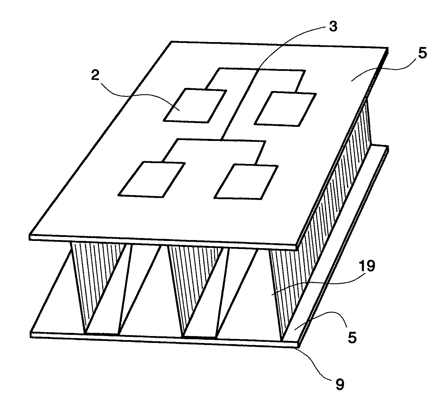
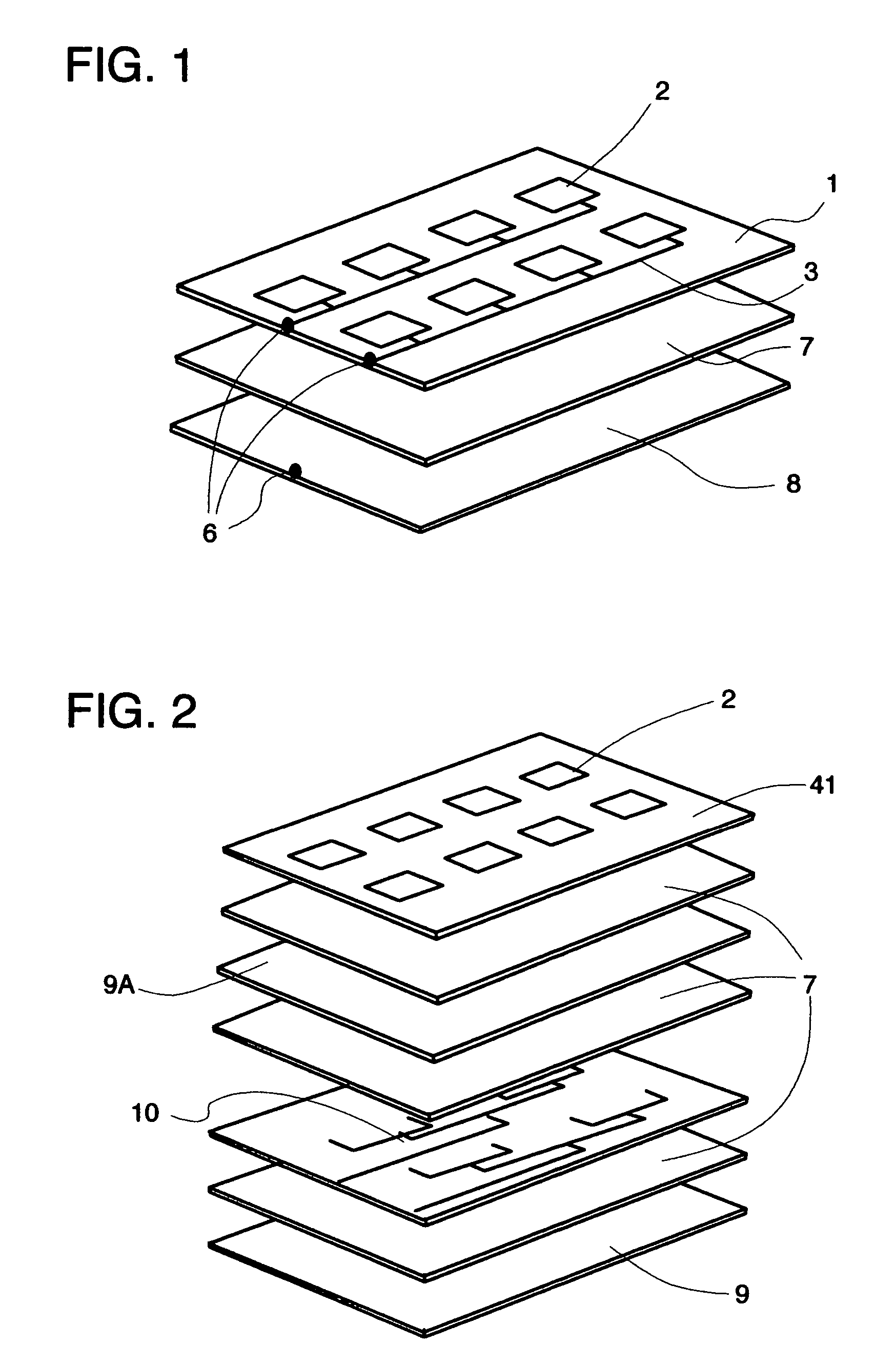
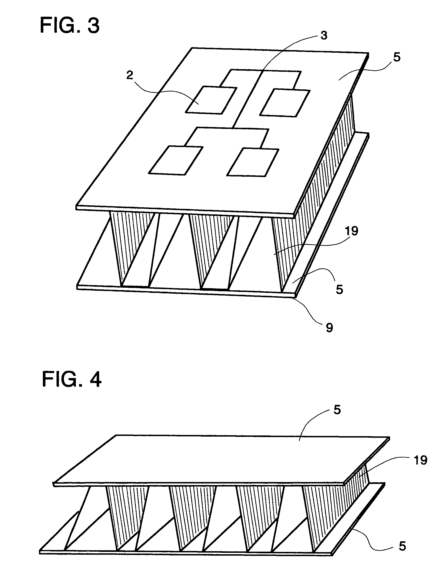
[0023]FIG. 1 is a rendition of the prior art three layer micro-strip antenna commonly employed for transmitting and receiving microwave radiation. This antenna is comprised of a first conductive patterned face layer 1 comprising a set of radiating patch antennas 2 and a set of feed lines 3 that carry energy from a connector means 6 to said patch antennas. While this is depicted as three different pieces (1, 2, 3), in reality the radiating patch layer is composed of a layer of copper that is either milled or acid etched to the desired shaped antenna patches and feed lines. This antenna layer is bonded to a dielectric spacer layer 7, usually composed of Teflon, and bonded to a third layer, the ground plane 8. The conductive portions of this antenna are connected to a receiver or transmitter or transceiver by a connector means 6.

[0024]FIG. 2 is a diagram of the current technology for a stripline antenna design which consists of a radiating layer 41 of antenna patches 2, dielectric spa...


PUM


Abstract

An Antenna comprising a ground layer, a feed layer, an antennal layer and a corrugated or dimpled non-woven fabric dielectric substrate interposed between two of the layers. The use of said non-woven corrugated fabric is to provide differing distances between the ground layer and the antenna layer as well as to provide both light weight construction and flexibility.

Description

TECHNICAL FIELD [0001] The present invention relates to an antenna for receiving or transmitting electromagnetic energy at or above microwave frequencies from or to a free space. The present invention more particularly relates to micro-strip patch or slot antennas. BACKGROUND OF THE INVENTION [0002] Patch and stripline antennas that are currently on the market usually comprise a radiating patch made of conductive material usually copper with feed lines attached to a dielectric spacer usually composed of Teflon and a ground plane again made of electrically conductive material and again this is usually copper. The ground plane and the radiating patches are attached to a connector. The radiating patches and feedlines are usually formed after the electrically conductive material in bonded to the Teflon dielectric spacer. The shapes are formed by either grinding away or by etching away with acid the undesired material. The groundplane is bonded to the other side of the dielectric space. ...

Claims


Application Information

Patent Timeline
Patent Type & Authority Applications(United States)
IPC IPC(8): H01Q1/38
CPCH01Q1/38H01Q21/065H01Q21/08
Inventor DEAETT, MICHAEL A.WEEDON, WILLIAM H. IIIPOURDEYHIMI, BEHNAM
Owner APPLIED RADAR
Why Eureka
Try Eureka