Optical element, laser light source, and two-dimensional image forming apparatus

a two-dimensional image and laser light source technology, applied in the direction of instruments, condensers, projectors, etc., can solve the problems of long life and low power consumption, and achieve the effects of reducing speckle noise, high coherency, and small size of optical elements

Inactive Publication Date: 2007-06-21
PANASONIC CORP
View PDF3 Cites 13 Cited by
  • Summary
  • Abstract
  • Description
  • Claims
  • Application Information

AI Technical Summary

Benefits of technology

[0046] According to an optical element of the present invention, since the optical element comprises a plurality of waveguides transmitting a light and a plurality of light path coupling parts coupling adjacent waveguides so as to optically couple said plural waveguides serially, and the paths for transmitting lights through the plural waveguides are curved at the optical path coupling parts, thereby it is possible to make the size the optical elements quite small and to obtain the effects which can be converted into the emitted light having uniform cross-sectional light intensity distribution by the optical element.
[0047] Further, since the plural waveguides have hollow structure, and either of gas or liquid and Brownian particles are sealed in the hollow of the waveguides, it is possible to reduce speckle noise that are generated in a laser light source having a high coherency.
[0048] According to a laser light source of the present invention, since the laser light source has integrated a semiconductor laser with the optical element, and has employed lens which collects or diffuses the laser light on an optical path between the laser light source and the semiconductor laser, it is possible to convert the spread angle of the light emitted from the optical element or to broaden the spread angle only in one axis direction of the incident light so that the cross-section light intensity distribution is made uniform, whereby it is possible to obtain the laser light source having a beam shape that is easy to handle.
[0049] Further in the laser light source, by having a lens which collects or diffuses the laser light before the optical element and selecting the curvature of the lens, it is possible to realize the laser light source which can accomplish a uniform output light cross-sectional intensity distribution with a short optical path length efficiently and can have an arbitrary output beam aspect ratio, thereby it is possible to increase the degree of freedom in designing the optical element.
[0050] In addition, according to a two-dimensional image forming apparatus of the present invention, since the two-dimensional image forming apparatus employs the laser light source, it is possible to obtain a effect that quite a compact two-dimensional image formation system which has quite simple parts constructions can be realized.

Problems solved by technology

In addition, it is also expected to apply a miniaturized high output laser light source to an illumination light source that is of low power consumption and has a lengthy lifetime.

Method used


Image

  • Optical element, laser light source, and two-dimensional image forming apparatus
  • Optical element, laser light source, and two-dimensional image forming apparatus
  • Optical element, laser light source, and two-dimensional image forming apparatus

Examples


embodiment 1

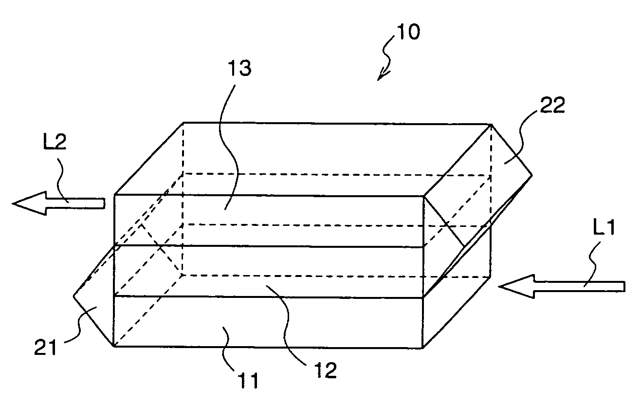
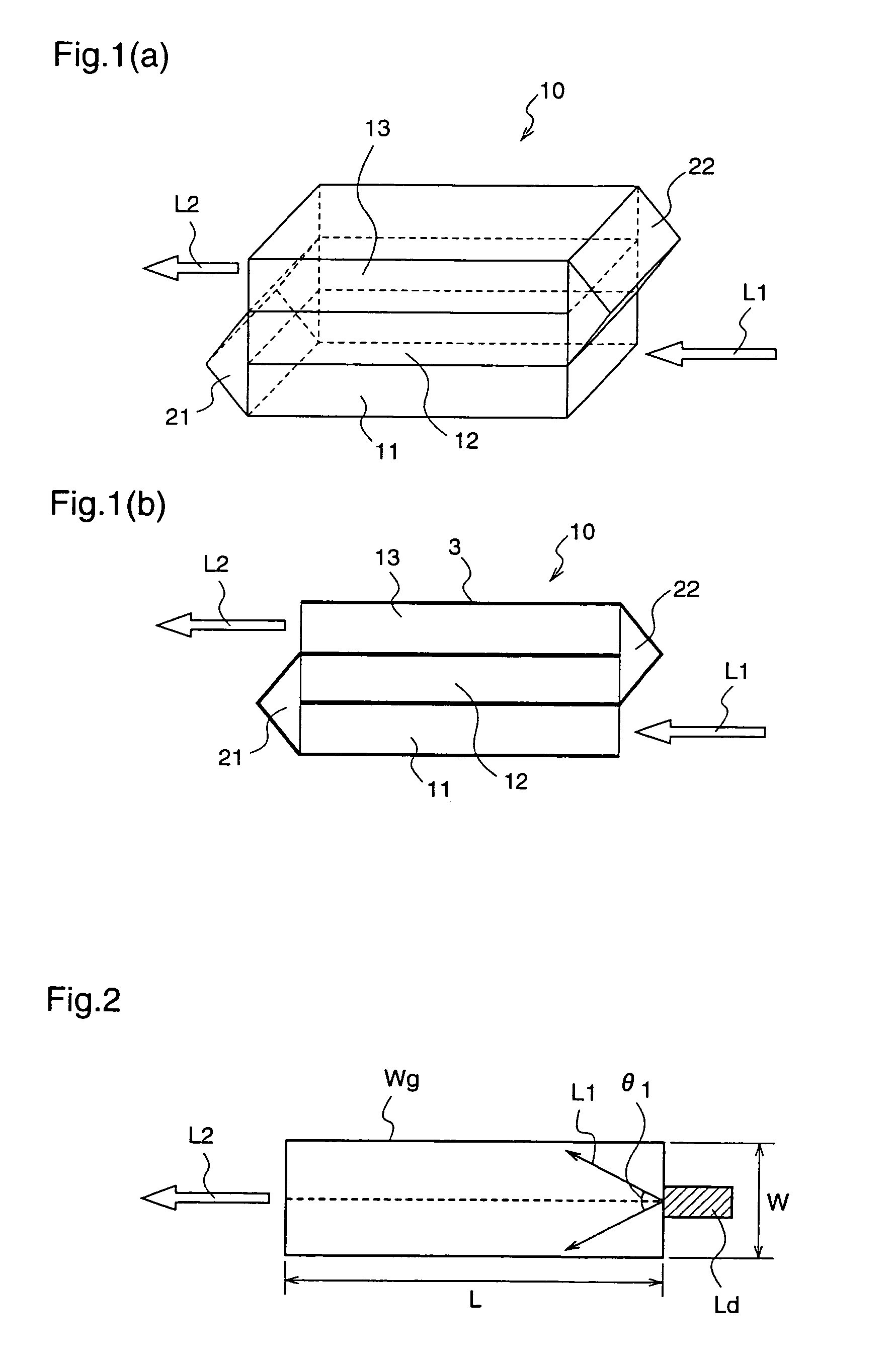
[0081] In this first embodiment, an optical element that has made the device size quite small by using plural waveguides and light path coupling parts which optically serially couples the waveguides.

[0082]FIG. 1 are diagrams for explaining an optical element according to a first embodiment of the present invention, FIG. 1(a) shows a cross-sectional view and FIG. 1(b) shows a perspective view.

[0083] The optical element 10 shown in FIG. 1 has first to third waveguides 11 to 13 having rectangular configurations comprising glass material transmitting incident light, and optical coupling parts 21, 22 coupling the respective waveguides 11 to 13 optically serially.

[0084] In this optical element 10, second and third waveguides 12 and 13 are successively stacked on the first waveguide 11 so that the light propagation directions in theses waveguides are parallel to each other, and the first waveguide 11 and the second waveguide 12 positioned thereon, and the second waveguide 12 and the thi...

embodiment 2

[0131]FIG. 5 shows an optical element according to a second embodiment of the present invention.

[0132] The optical element 20 of this second embodiment is constituted by serially coupling the respective waveguides of the optical element 10 of the first embodiment, without using a prism.

[0133] More particularly, the optical element 20 shown in FIG. 5 has a first waveguide 21 which has an end surface that is inclined by 45 degree with respect to the light propagation direction in the waveguide, a second waveguide 22 which has both end surfaces that are respectively inclined by 45 degree with respect to the light propagation direction of the waveguide, and a third waveguide 23 which has an end surface that is inclined by 45 degree with respect to the light propagation direction.

[0134] Here, the inclined surface 21a at an end side of the first waveguide 21 is a reflection plain that reflects the light propagating in the waveguide to be reflected along the waveguide height direction. ...

embodiment 3

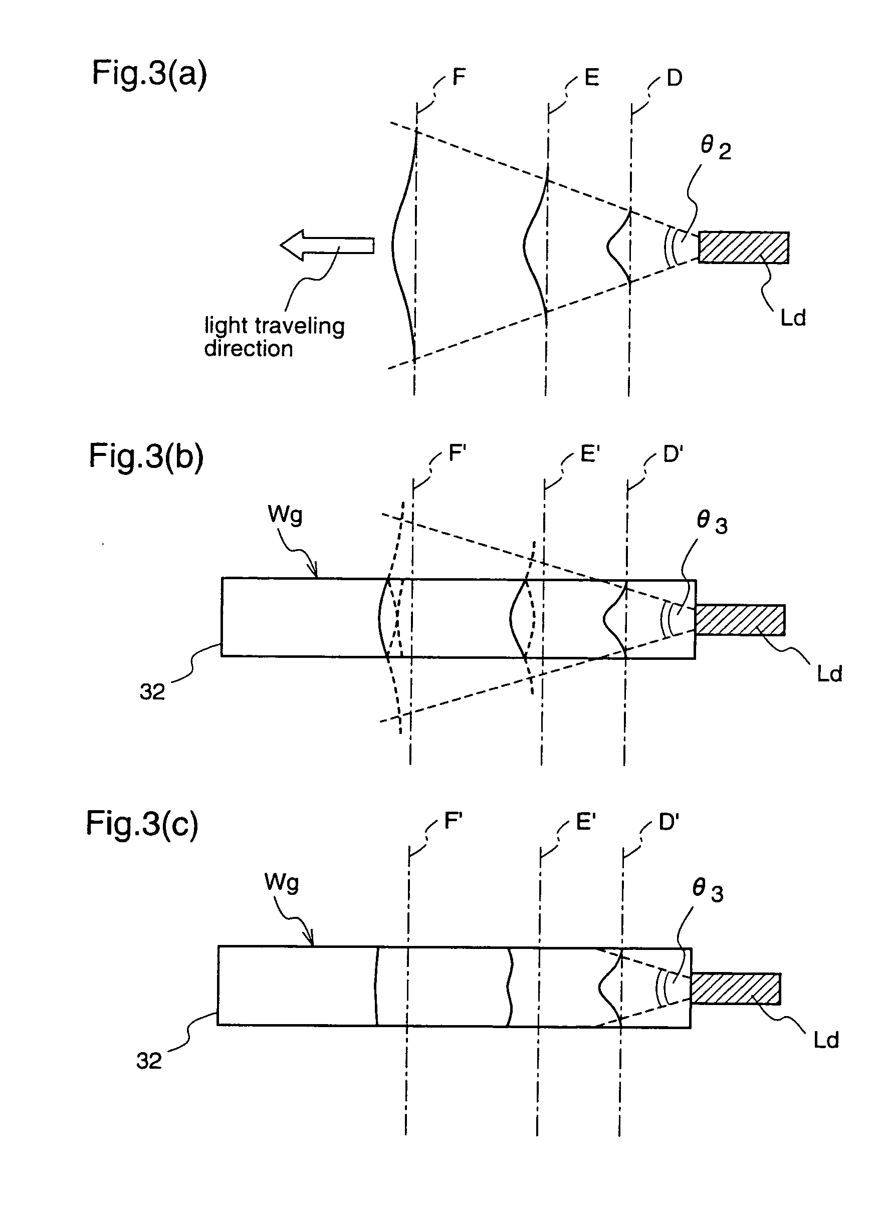
[0142]FIG. 6 is a perspective view illustrating an optical element according to a third embodiment of the present invention.

[0143] The optical element 30 of this third embodiment is constituted having first to third waveguides 31 to 33 having rectangular configurations comprising glass material transmitting incident light, and optical coupling parts 21, 22 coupling the respective waveguides 31 to 33 optically serially.

[0144] In this optical element 30, second and third waveguides 32 and 33 are successively stacked on the first waveguide 31 so that the light propagation directions in theses waveguides are parallel to each other, and the first waveguide 31 and the second waveguide 32, and the second waveguide 32 and the third waveguide 33 are respectively optically coupled by a rectangular prism 21 which serves as an optical path coupling part and a rectangular prism 22 which serves as an optical path coupling part, respectively.

[0145] In this third embodiment, the respective waveg...


PUM


Abstract

An optical element (10) according to the present invention is provided with a plurality of waveguides (11)˜(13) and a plurality of light path coupling parts (21), (22) coupling adjacent waveguides so as to optically couple said plural waveguides serially, wherein the paths for transmitting lights through the plural waveguides are curved at the optical path coupling parts, thereby the optical elements which is converted the incident laser light into the emitted light having uniform cross-sectional light intensity distribution can give a compact structure, further a laser light source that employs the optical element, and a two-dimensional image forming apparatus that employs the laser light source can also give a compact structure.

Description

TECHNICAL FIELD [0001] The present invention relates to an optical element, a laser light source, and a two-dimensional image forming apparatus and, more particularly, to an optical element that converts an incident light to an emitted light that has a uniform emitted light intensity distribution, a laser light source employing the optical element, and a two-dimensional image forming apparatus employing the laser light source. BACKGROUND ART [0002] Up to now, the laser light source is mainly applied in the fields of measurements, optical communication, optical discs, and the like which utilize the collecting characteristics of laser light as well as high coherency. However, the research and developments of laser light sources are eminent and small-sized high output lasers represented by semiconductor lasers are advancing in their practical uses, and there are such as multi-mode semiconductor lasers which can accomplish outputs of several watts order in semiconductor lasers. [0003] A...

Claims


Application Information

Patent Timeline
Patent Type & Authority Applications(United States)
IPC IPC(8): G02B6/42G02B27/09G03B21/20
CPCG02B6/4214G02B27/0994G03B21/2033G03B21/208G02B19/0052G02B19/0028
Inventor SUGITA, TOMOYAMIZUUCHI, KIMINORIKASAZUMI, KEN'ICHIMORIKAWA, AKIHIRO
Owner PANASONIC CORP
Why Eureka
Try Eureka