Connector

a technology of connecting parts and connectors, applied in the direction of coupling contact members, coupling device connections, coupling/disconnecting parts, etc., can solve the problems of higher cost of production than molded products, increase in the number of components, and higher cos

Active Publication Date: 2007-06-21
JST MFG CO LTD
View PDF30 Cites 25 Cited by
  • Summary
  • Abstract
  • Description
  • Claims
  • Application Information

AI Technical Summary

Benefits of technology

[0053] The connector provides a connector for a printed circuit board surface-mounted onto the printed circuit board by soldering the plurality of first and second lead portions to the printed circuit board. Furthermore, the first lead portion and the second lead portion are disposed in an opposing direction, therefore, a pitch between patterns connected to the first and second lead portions can be increased more than the case of the first and sec

Problems solved by technology

However, such integrally molded products including metal members cause higher costs in production than molded products made of synthetic resin alone.
As a matter of course, an increase in the number of components causes higher costs.
This is because supporting a meta

Method used


Image

  • Connector
  • Connector
  • Connector

Examples


Embodiment Construction

[0070] With reference to the drawings, the best mode for carrying out the invention will be described hereinafter.

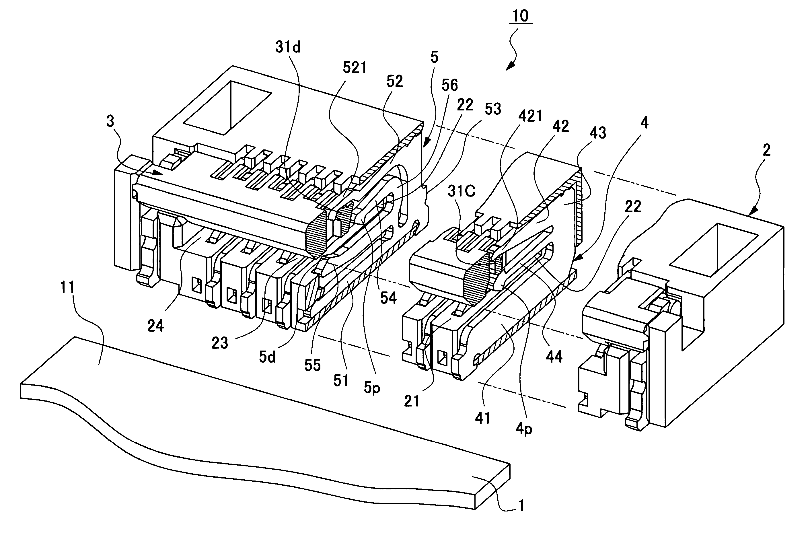
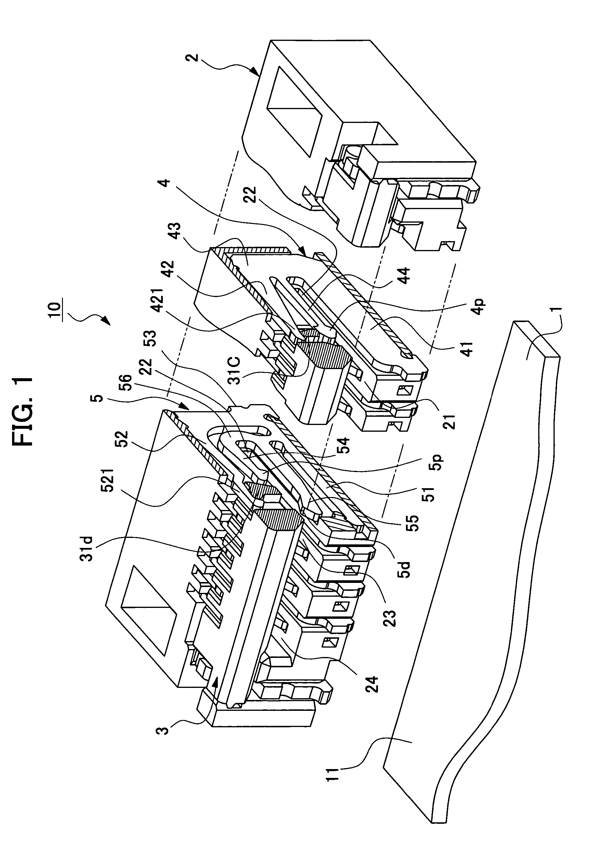
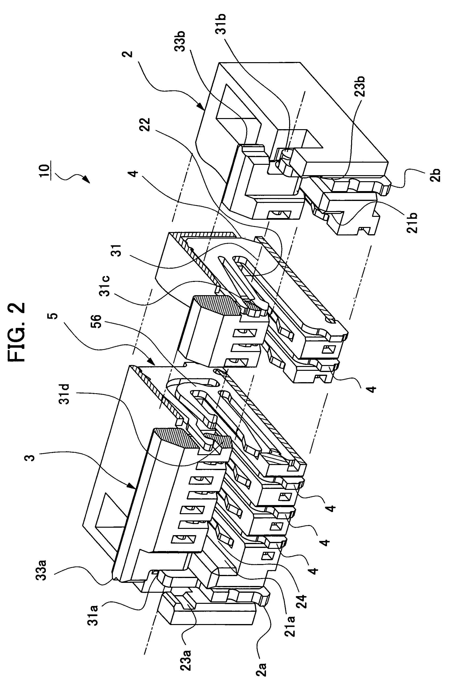
[0071]FIG. 1 is a perspective outline view showing an embodiment of a connector for an FPC, hereinafter referred to as a connector, according to the present invention. FIG. 1 is a state view of a closed cover housing in which the principal parts are cross-sectionally shown. FIG. 2 is a perspective outline view of a connector according to the present invention, in a state where the cover housing is open. FIG. 3 is a plan view of a connector according to the present invention, in a state where the cover housing is open. FIG. 4 is a front view of a connector according to the present invention, in a state where the cover housing is open.

[0072]FIG. 5 is a longitudinal sectional view (a longitudinal sectional view taken on line W-W of FIG. 4) in which the side surface of the first contact of a connector according to the present embodiment is cross-sectionally shown, in a sta...


PUM


Abstract

A connector of upper contact type for an FPC comprising a cover housing constituted of synthetic resin alone. The housing includes first contacts and second contacts alternately arranged in parallel on a line. Each of the first contacts has an elastic arm coming into contact with an upper contact point of FPC when the cover housing is closed. On the other hand, each of the second contacts has a tuning-fork-shaped contact constituted of a pair of a short arm and a long arm, the short arm coming into contact with the upper contact point of the FPC so that the tuning-fork-shaped contact may exert a coupled force on the FPC when the cover housing is closed. With such a configuration, this connector reduces deformation of the cover housing while eliminating use of any reinforcing metal member in the cover housing.

Description

[0001] This application is based on and claims the benefit of priority from Japanese Patent Application No. 2005-362781, filed on Dec. 16, 2005, the content of which is incorporated herein by reference. BACKGROUND OF THE INVENTION [0002] 1. Field of the Invention [0003] The present invention relates to a connector to be connected with a flat flexible cable such as an FPC (Flexible Printed Circuit) and an FFC (Flexible Flat Cable), which are generically called FPC in this specification, and particularly to a ZIF (Zero Insertion Force) type connector for a FPC which requires little force for insertion and removal of the FPC. [0004] 2. Related Art [0005] A connector for an FPC to be surface-mounted on a printed circuit board, or a surface mount connector for an FPC has an insulated housing formed with an insertion portion for inserting the FPC and a plurality of contacts fitted onto the housing side by side in a line at predetermined pitches. To bring the FPC into touch with the contac...

Claims


Application Information

Patent Timeline
IPC IPC(8): H01R12/24H01R12/79
CPCH01R12/57H01R12/79H01R12/88
Inventor MIURA, KAZUTOFUNAKOSHI, AKIHITO
Owner JST MFG CO LTD
Why Eureka
Try Eureka