Drug eluting stent for the treatment of dialysis graft stenoses

a stenose and dialysis technology, applied in the field of drug eluting stents for the treatment of dialysis graft stenoses, can solve the problems of graft failure, limited number of sites for patients, and short graft li

Inactive Publication Date: 2007-06-21
ABBOTT CARDIOVASCULAR
View PDF15 Cites 51 Cited by
  • Summary
  • Abstract
  • Description
  • Claims
  • Application Information

AI Technical Summary

Problems solved by technology

Unfortunately, these grafts do not last long since they develop thrombosis and restenosis, particularly at the distal anastamosis.
After a few stenoses, the graft is considered a failure, requiring that the physician close the graft down and create a new one.
Unfortunately, patients only have a limited number of sites where these grafts can be placed.
It can also dull the needle, making it impossible to enter so that the needle has to be removed and reinserted, causing more trauma to the graft.

Method used


Image

  • Drug eluting stent for the treatment of dialysis graft stenoses
  • Drug eluting stent for the treatment of dialysis graft stenoses
  • Drug eluting stent for the treatment of dialysis graft stenoses

Examples


Embodiment Construction

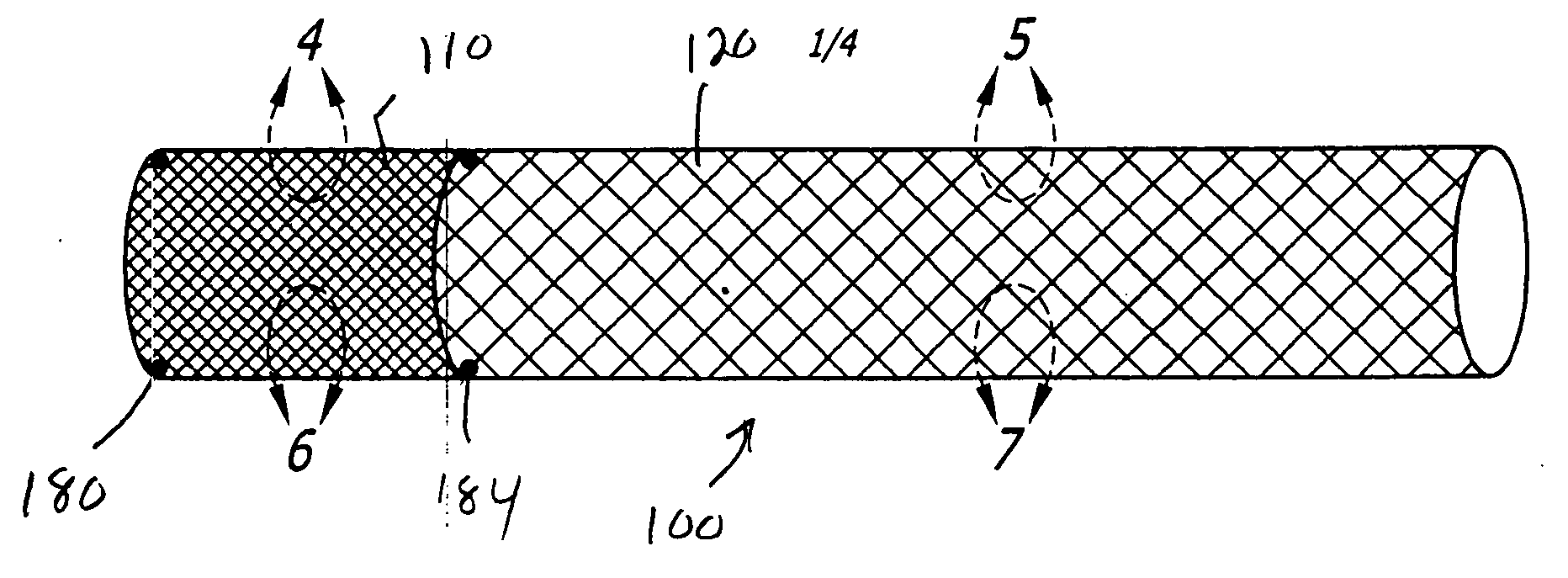
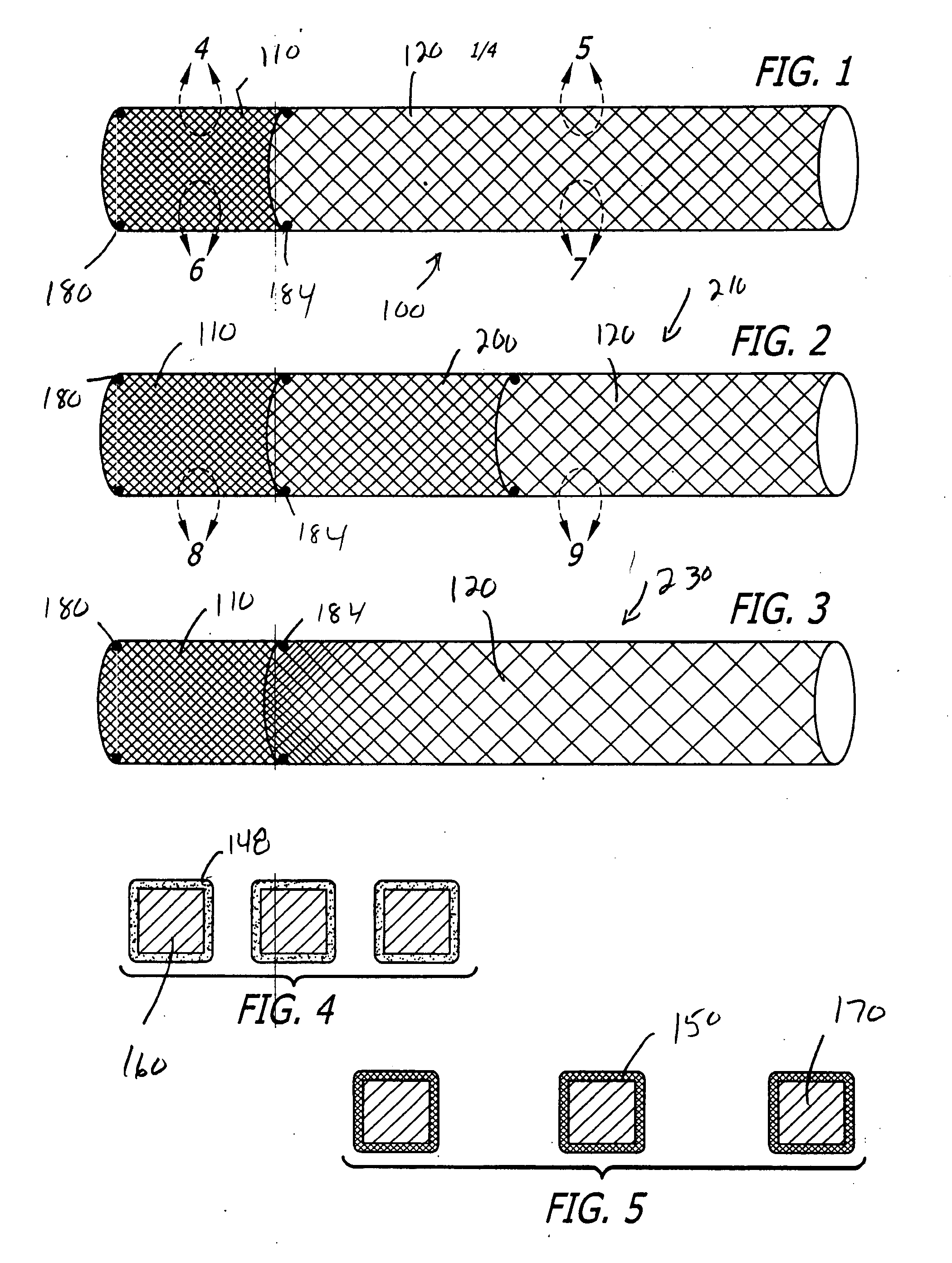
[0024] A stent of the present invention is illustrated schematically in FIG. 1, generally at 100, and can be balloon-expandable or self-expandable. As discussed in detail later and with reference to FIGS. 12 and 13, it can be a dialysis graft stent or an arterial venous anastomosis stent. Stent 100, which is preferably formed as a single unitary construction, includes two zones or portions, and can be formed by laser cutting a hypo tube as would be apparent to those skilled in the art from this disclosure. The first portion is shown on the left side of FIG. 1 generally at 110 and a (longer) second portion is shown on the right side generally at 120. The stent 100 can be formed with generally any strut and link configuration as is known. The stent 100, when expanded, can have an internal diameter of between four and eight mm and a length between fifteen and seventy mm, or more particularly, a diameter of approximately six mm and a length of approximately thirty mm.

[0025] The first p...


PUM


Abstract

A drug-eluting stent having a first cell pattern at one end and a second cell pattern on an opposite end. The cells in the first cell pattern have a smaller MCUSA than those in the second cell pattern. An anti-restonic drug can be coated on the first cell pattern and an anti-thrombotic drug on the second, with the anti-thrombotic drug overlaying and covering both the first and second cell patterns. The stent is operatively positionable at a distal graft-vein anastomosis with the first cell pattern adjacent the stenosis, and with the second cell pattern positioned adjacent the vein or the graft.

Description

BACKGROUND OF THE INVENTION [0001] In the late stages of kidney disease it is often necessary for patients to repeatedly undergo dialysis where their blood is removed, cleansed in a dialysis machine and then returned to their bloodstream. Since arteries cannot be punctured numerous times during a dialysis process and remain functional, grafts are used. The grafts are implanted just below the patient's skin, typically on the patient's arm, to give the physician easy access to the artery and vein and the circulating blood. The graft can be easily palpated and punctured easily with needles so that the dialysis technician can access the patient's bloodstream. [0002] Unfortunately, these grafts do not last long since they develop thrombosis and restenosis, particularly at the distal anastamosis. Wherever a graft is inserted, an injury repair process occurs, typically at the distal anastamosis where there is initially some thrombosis forming a matrix deposit. The cells migrate into that a...

Claims


Application Information

Patent Timeline
Patent Type & Authority Applications(United States)
IPC IPC(8): A61F2/06A61F2/86A61F2/90
CPCA61F2/86A61F2/90A61F2/91A61F2250/0023A61F2250/0035A61F2250/0036A61F2250/0067A61M1/3655A61F2/82
Inventor CONSIGNY, PAULKRAUSA, TRACEYMERKERT, MATTHEW C.
Owner ABBOTT CARDIOVASCULAR
Why Eureka
Try Eureka