Method and apparatus for treating refuse with steam

a technology of steam treatment and refuse, which is applied in the direction of lighting and heating equipment, manufacturing tools, furniture, etc., can solve the problems of organic refuse that remains dormant for decades, groundwater contamination, and unfavorable decomposition of organic refuse, so as to increase the overall humidity of the landfill, increase the btu value, and improve the effect of btu

Inactive Publication Date: 2007-06-28
RENAUD REGIS P
View PDF38 Cites 11 Cited by
  • Summary
  • Abstract
  • Description
  • Claims
  • Application Information

AI Technical Summary

Benefits of technology

[0012] The method of injecting steam into landfills according to this invention has several features, no single one of which is solely responsible for its desirable attributes. Without limiting the scope of this invention as expressed by the claims that follow, its more prominent features will now be discussed briefly. After considering this discussion, and particularly after reading the section entitled “Detailed Description of the Drawings,” one will understand how the features of this invention provide advantages, which include minimization of the amount of liquid introduced into the landfill, total moisturization and higher overall humidity of the landfill without the need to apply head pressure, promotion of settlement of the landfill, heating of the refuse, avoidance of clogging of gas extraction collectors, ability to distribute gaseous anaerobic fertilizer throughout the trash prism, increased methane production, and production of methane having higher Btu values as compared to methane produced in other landfills.
[0013] The present method comprises injecting steam into a landfill and collecting the methane produced by the decomposition / biodegradation of the organic component of the trash prism. The steam accelerates the decomposition of the organic refuse, thereby enhancing methane gas production by increasing the purity of the methane. By accelerating the decomposition of the organic refuse, the steam also increases the rate of settlement of the landfill. The time necessary to convert the landfill into property that is useful for purposes besides waste disposal is thus reduced. The reduced decomposition time also reduces the impact of the landfill on the environment.

Problems solved by technology

However, dry conditions are not conducive to the decomposition of the organic refuse.
Instead, the organic refuse remains dormant for decades until water infiltrates the landfill in an uncontrolled and natural manner.
The water infiltration may cause gas migration, which can lead to groundwater contamination.
The slow decomposition of the organic refuse under dry conditions also slows the settling of the landfill and hinders the production of methane gas, which is a natural by-product of anaerobic (oxygen-starved) decomposition of organic material.
Delaying the complete settling of a landfill is disadvantageous, because until the landfill settles, the landfill site is not useful for any purpose other than a garbage dump.
Moisture accelerates decomposition of organic refuse, but does not accelerate the decomposition of the non-organic refuse.
If the refuse is flooded with water, however, the gas becomes bound up in the liquid and is difficult to recover.
Further, introducing water after a landfill has been closed cools the refuse.
The non-uniform distribution of liquid around these layers only causes the biodegradation of the organic material in the immediate area of the liquid, rather than throughout the entire trash prism.
The Cosulich method, however, does not suggest the benefits gained by increasing the moisture content of the landfill, or address the detrimental effects of lowering the temperature of the landfill by introducing water.
The Hudgins method thus does not provide a convenient way to produce methane for beneficial purposes.

Method used


Image

  • Method and apparatus for treating refuse with steam
  • Method and apparatus for treating refuse with steam
  • Method and apparatus for treating refuse with steam

Examples


Embodiment Construction

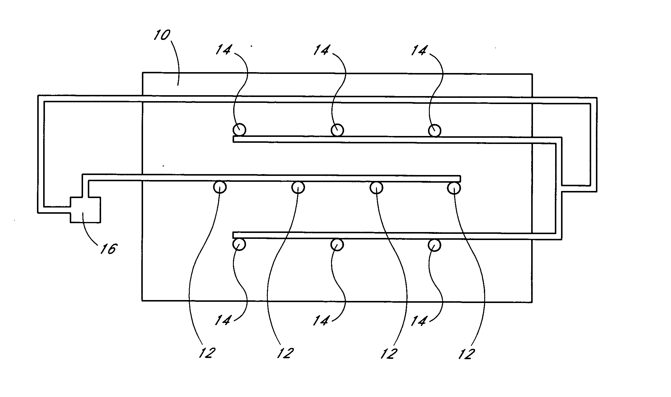
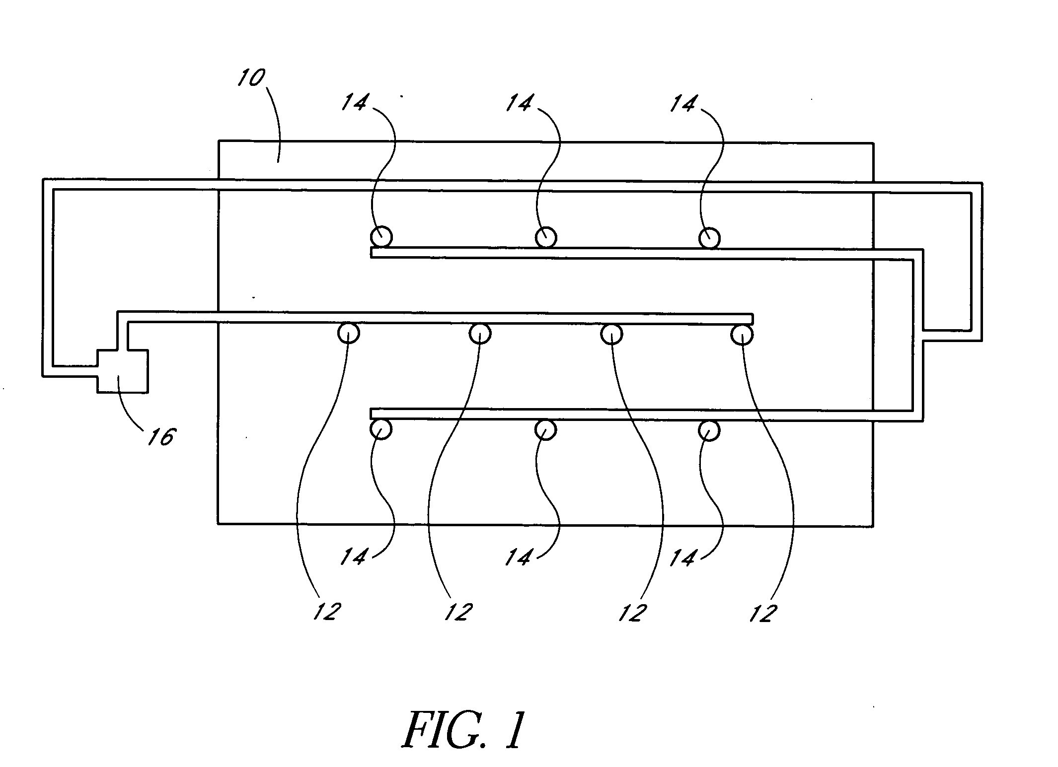
[0039] In an embodiment of the present methods and apparatus, steam is injected into a landfill 10. The steam promotes the anaerobic biodegradation of the organic refuse in the landfill 10, which in turn increases methane gas generation and increases the rate of settlement of the landfill 10.

[0040]FIG. 1 schematically illustrates an apparatus for performing an embodiment of the present method. Several lines of steam injection wells 12 and several lines of gas extraction collectors 14 are positioned within a landfill 10. The arrangement depicted in FIG. 1 is merely exemplary. The ideal location for the injection wells 12 and gas collectors 14 is preferably determined prior to installing the steam injection apparatus, and may differ significantly from the arrangement of FIG. 1.

[0041] One preferred method of determining the ideal location for the steam injection wells 12 and gas collectors 14 is to perform a piezo-penetrometer test (PPT) profile on the landfill 10. The PPT profile is...


PUM


Abstract

A method of injecting steam into a landfill is provided. The steam enhances methane gas production in the landfill during the anaerobic phase, accelerates decomposition / biodegradation of the organic component of the trash prism during both the aerobic and anaerobic phases, and increases the rate of settlement of the landfill. A method of introducing a gaseous anaerobic fertilizer into the landfill is also provided. The fertilizer accelerates the decomposition / biodegradation of the organic component of the trash prism. A method of reducing the volume of a plastic component of the trash prism is provided, wherein the temperature and pressure of injected steam are raised to a level sufficient to melt plastic. Methods and apparatus for reducing the volume of a quantity of refuse prior to placing the refuse in a landfill are provided. The refuse is heated with steam and also compacted. The heat melts plastic in the refuse, and the compaction increases the quantity of refuse that can be placed into a given landfill.

Description

RELATED APPLICATIONS [0001] This application is a divisional of U.S. application Ser. No. 10 / 778,012, filed on Feb. 12, 2004, which is a continuation-in-part of U.S. application Ser. No. 10 / 283,399, filed on Oct. 29, 2002, abandoned, which is a divisional of U.S. application Ser. No. 09 / 838,442, filed on Apr. 19, 2001, now U.S. Pat. No. 6,471,443, which claims the benefit of U.S. Provisional Application Ser. No. 60 / 198,196, filed on Apr. 19, 2000. All of the priority applications are incorporated herein by reference.BACKGROUND OF THE INVENTION [0002] 1. Field of the Invention [0003] The present invention relates to methods and apparatus for treating refuse, both before and after the refuse is placed in a landfill. [0004] 2. Description of the Related Art [0005] In general, landfills are constructed using the “dry tomb” method, in which the refuse in the landfill is kept as dry as possible both during construction and when the landfill is closed and capped. This method minimizes the ...

Claims


Application Information

Patent Timeline
Patent Type & Authority Applications(United States)
IPC IPC(8): F26B19/00F26B3/00B09B1/00B09B3/00
CPCB09B1/00B09B3/00B09B3/0025C12M29/26B30B9/3035C12M21/04C12M29/06B09B3/0083B09B3/20B09B3/40
Inventor RENAUD, REGIS P.
Owner RENAUD REGIS P
Why Eureka
Try Eureka