Multi-layered flexible print circuit board and manufacturing method thereof

a flexible print circuit board and multi-layer technology, applied in the direction of manufacturing tools, stacked and attached pcbs, conductive pattern formation, etc., can solve the problems of circuit layer, difficult to finely pattern the conduct pattern of the electrically-conductive layer at the subsequent etching step, and limited methods. , to achieve the effect of high connection reliability and high productivity

Inactive Publication Date: 2007-06-28
PANASONIC CORP
View PDF14 Cites 20 Cited by
  • Summary
  • Abstract
  • Description
  • Claims
  • Application Information

AI Technical Summary

Benefits of technology

[0013] In accordance with this producing method, the deformation of the metal layer on the surface of the electrically-conductive member allows the electrically-conductive member to make firm and close connection to the circuit layer and the through-hole, making it possible to obtain a high connection reliability. Further, since interlayer connection is made after the formation of the circuit layer, the process has no effect

Problems solved by technology

However, this method is limited in its capability and leaves something to be desired.
The flexible print circuit board obtained by the aforementioned plated through-hole method is disadvantageous in that thick copper plating causes the rise of the thickness of not only the copper deposit layer on the inner wall of the through-hole but also the copper foil constituting the electrically-conductive layer, making it difficult to finely pattern the conduct pattern of the electrically-conductive layer at the subsequent etching step.
Further, the

Method used


Image

  • Multi-layered flexible print circuit board and manufacturing method thereof
  • Multi-layered flexible print circuit board and manufacturing method thereof
  • Multi-layered flexible print circuit board and manufacturing method thereof

Examples


embodiment 1

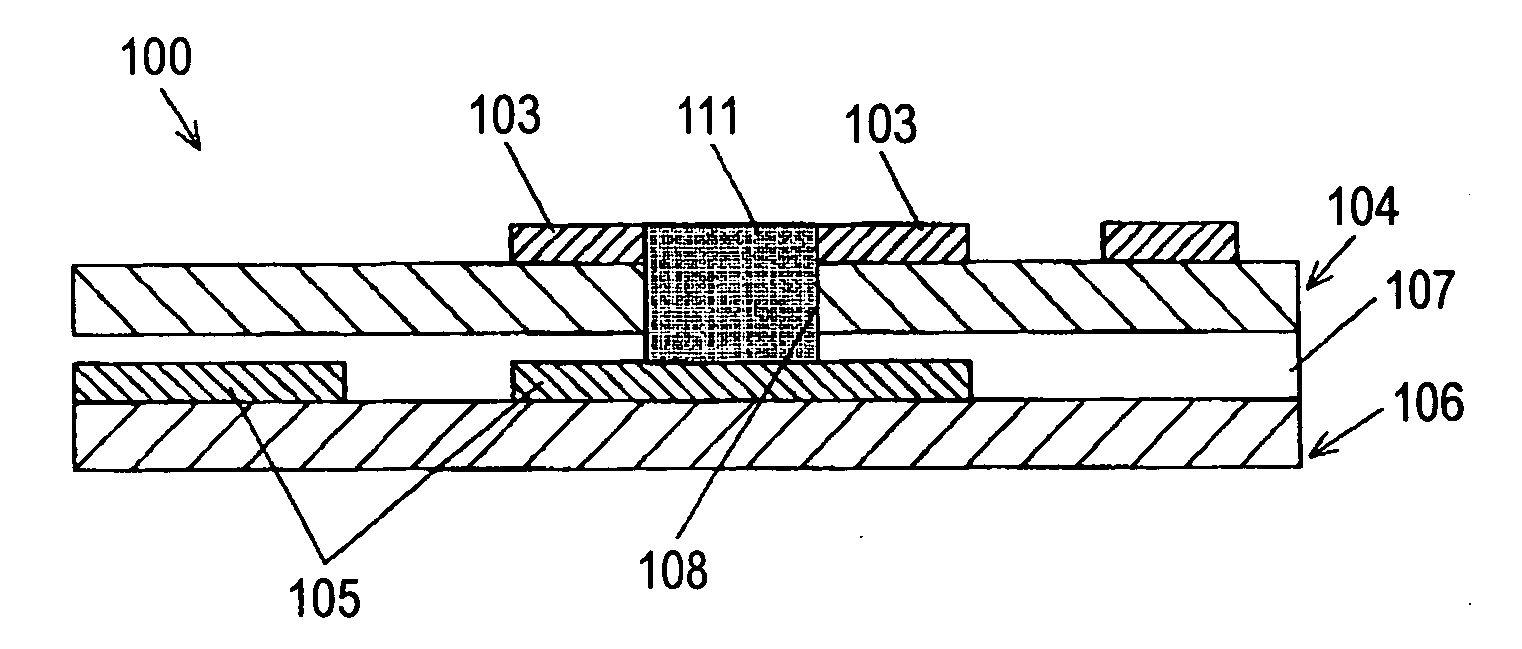
[0110] A multi-layered FPC according to en embodiment of implementation of the invention will be described hereinafter. Firstly, the multi-layered FPC of the invention will be described in connection with FIG. 1. FIG. 1 is a side sectional view of an essential part of a multi-layered FPC according to an embodiment of implementation of the invention.

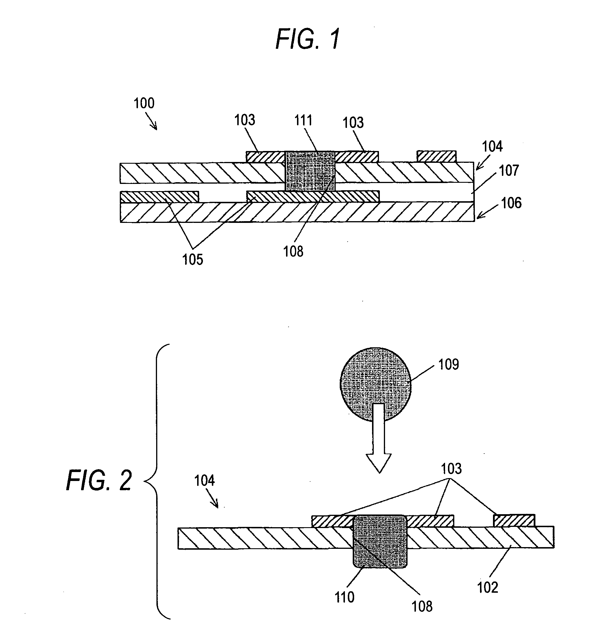
[0111] In FIG. 1, the reference numeral 100 indicates a multi-layered FPC obtained by laminating a one-sided circuit board 104 having an upper circuit layer 103 provided on one side of an insulating layer 102 made of polyimide film and another one-sided circuit board 106 having a lower circuit layer 105 with an adhesive layer 107 interposed therebetween (The upper circuit layer 103 and the lower circuit layer 105 will be hereinafter occasionally referred generically to as “circuit layer”). The one-sided circuit board 104 has a through-hole 108 formed therein extending through the insulating layer 102 and the upper circuit layer 103. Thou...

embodiment 2

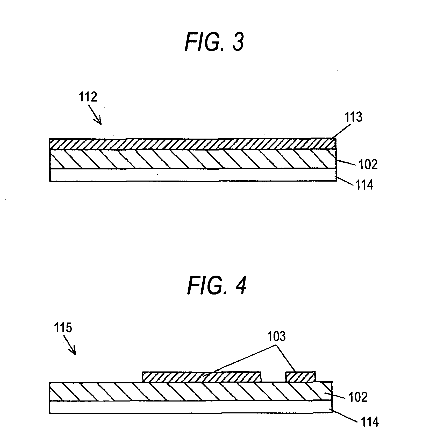
[0138] Embodiment 2 will be described in detail with reference to a method of producing a multi-layered FPC according to another embodiment of implementation of the invention excellent in reliability of connection between circuit layers and fine patterning of circuit layer at a good productivity in connection with FIGS. 14 to 20. FIG. 14 is a sectional view of an essential part of a multi-layered FPC according to an embodiment of implementation of the invention. FIG. 15 is a sectional view of an essential part of a one-sided circuit board with an adhesive sheet which is a constituent element of a multi-layered FPC according to an embodiment of implementation of the invention. FIG. 16 is a sectional view of an essential part of a one-sided circuit board with an adhesive sheet having a circuit layer according to en embodiment of implementation of the invention formed thereon. FIG. 17 is a sectional view of an essential part of a one-sided circuit board with an adhesive sheet having a ...

embodiment 3

[0154] Embodiment 3 will be described hereinafter with reference to a multi-layered FPC according to the invention obtained by further laminating the aforementioned multi-layered FPC. FIG. 21 is a sectional view of an essential part of a multi-layered FPC which has been finished in lamination according to an embodiment of implementation of the invention. FIG. 22 is a sectional view of an essential part of a multi-layered FPC in the course of lamination according to an embodiment of implementation of the invention. FIG. 23 is a sectional view of an essential part of another multi-layered FPC which has been finished in lamination according to an embodiment of implementation of the invention.

[0155] Firstly, in FIG. 21, the reference numeral 300 indicates a multi-layered FPC obtained by laminating the multi-layered FPC 100a produced by the aforementioned method of producing a multi-layered FPC according to Embodiment 1 and the one-sided circuit boards 24a, 24b, 24c and 24d with an adhe...


PUM

PropertyMeasurementUnit
Flexibilityaaaaaaaaaa
Strengthaaaaaaaaaa

Abstract

Provided is an FPC, which comprises an insulating layer 2, wiring layers 3 and 4 laminated above and under the insulating layer 2, and a layer connection for connecting the wiring layers 3 and 4 electrically. The layer connection is constituted to comprise: a conductor press-fit hole 5 of a cone shape extending through the insulating layer 2 and the upper and lower wiring layers 3 and 4 and expanded to the side of one wiring layer 3; and a conductor 6 filled and press-fitted without any clearance in the conductor press-fit hole such that it is jointed to the wiring upper layer 3 deformed into the cone shape of the conductor press-fit hole 5, and is protruded from the other wiring lower layer 4 to have its surface partially coated and jointed. As a result, the contact area between the wiring layers 3 and 4 and the conductor 6 filled in the conductor press-fit hole 5 can be enlarged to retain the contact strength between the wiring layers 3 and 4 and the conductor 6 sufficiently thereby to provide a high connection reliability for the layer connection.

Description

BACKGROUND OF THE INVENTION [0001] The present invention relates to a flexible print circuit board (hereinafter referred to as “FPC”) having various surface mountable electronic parts mounted thereon and a method of producing the same and more particularly to a multi-layered FPC having high connection reliability and a method of producing the same. [0002] With the recent trend for smaller size, lighter weight and higher performance of electronic apparatus, the circuit density of FPC to be incorporated therein tends to increase more and more. As a method of increasing the circuit density of FPC, there is used a method involving fine patterning of circuit layer. However, this method is limited in its capability and leaves something to be desired. Under these circumstances, a multi-layered FPC obtained by laminating circuit layers on each other with an adhesive layer interposed therebetween and providing the insulating layer between the circuit layers with an interlayer connection stru...

Claims


Application Information

Patent Timeline
IPC IPC(8): H01L21/82
CPCH05K1/0393Y10T29/49155H05K3/4046H05K3/4084H05K3/4614H05K3/4617H05K3/462H05K3/4623H05K3/4635H05K2201/0195H05K2201/0221H05K2201/0379H05K2201/043H05K2201/096H05K2201/10234H05K2201/10416H05K2203/0278H05K2203/041H05K2203/082Y10T29/49117Y10T29/49213Y10T29/49165Y10T29/49126H05K3/386
Inventor YOSHINO, TOYOKAZUOKAMOTO, KATSUYAOGATA, SHIGEKIMORIMOTO, SHINJINAKASHIMA, KOUJI
Owner PANASONIC CORP
Why Eureka
Try Eureka