Bipolar high frequency treatment device
- Summary
- Abstract
- Description
- Claims
- Application Information
AI Technical Summary
Benefits of technology
Problems solved by technology
Method used
Image
Examples
first embodiment
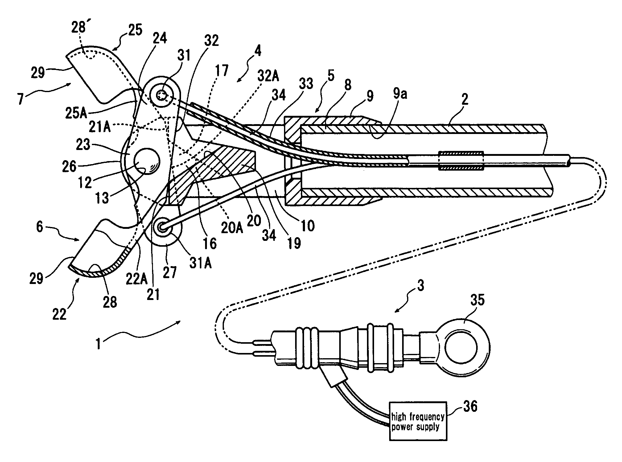
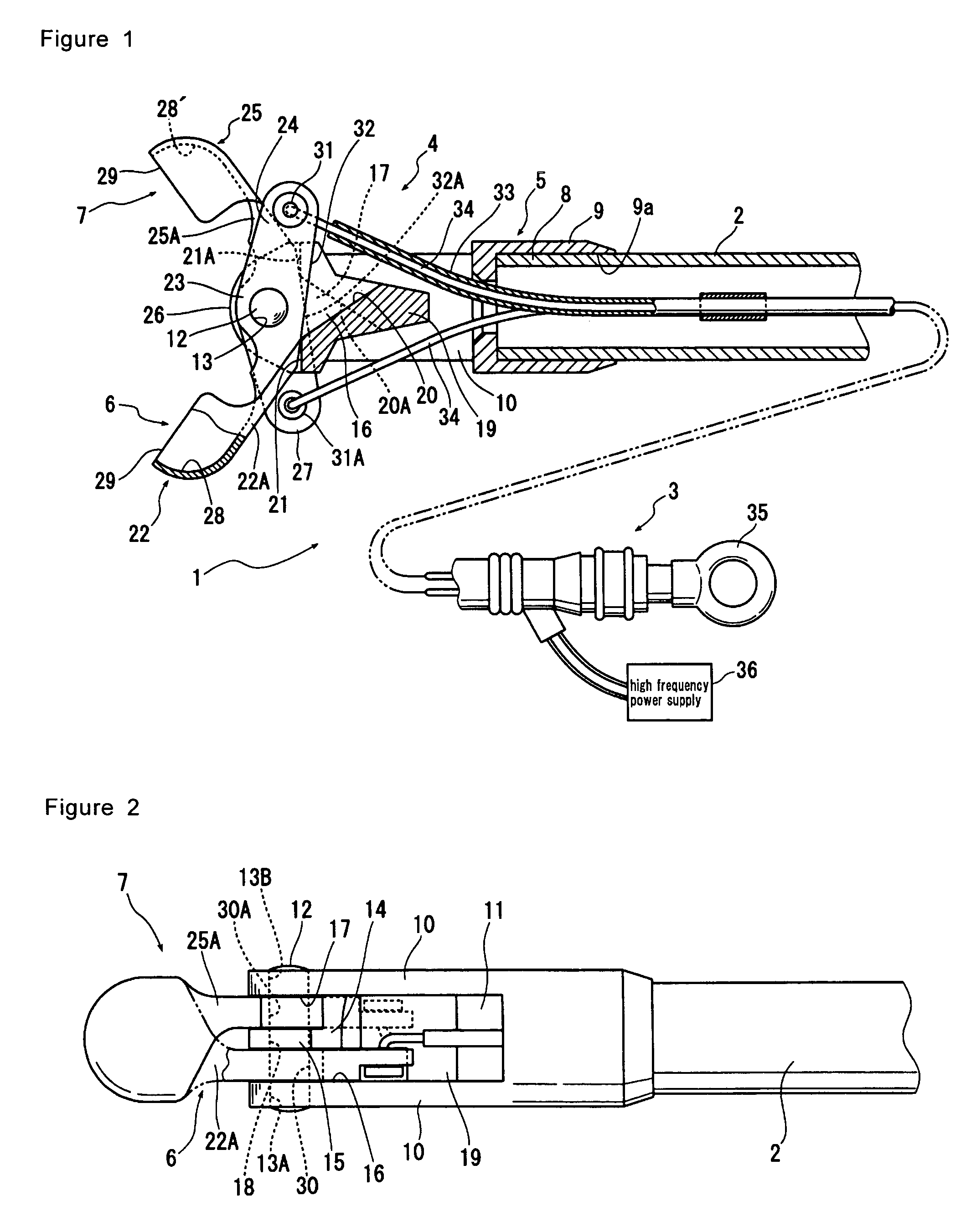
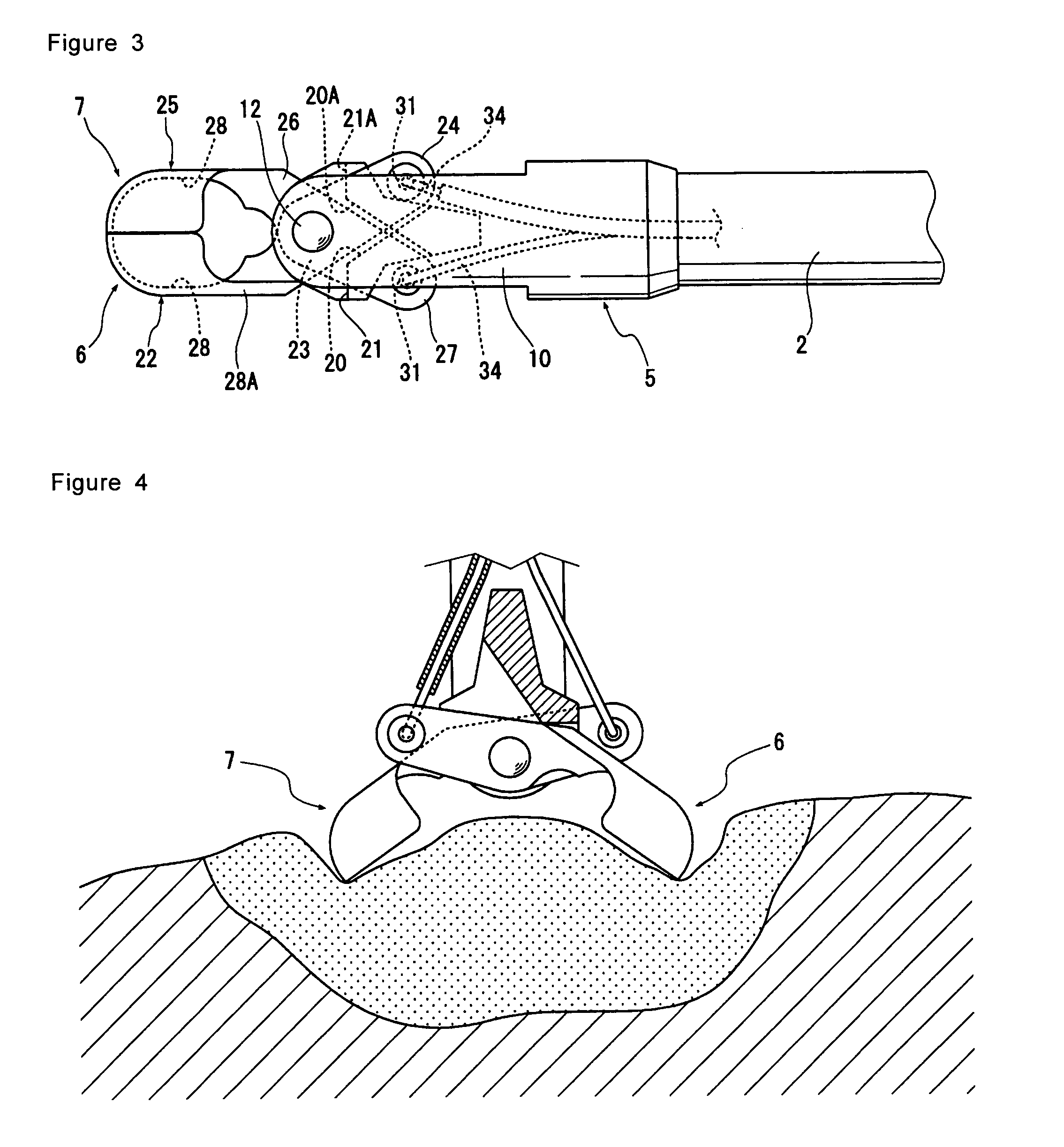
[0048] As shown in FIG. 1, a bipolar high frequency treatment device 1 according to the first embodiment of the present invention comprises a catheter tube 2, which is, for example, which can be inserted into a stomach and a large intestine in the body through a treatment device passage in an endoscope (not shown). This catheter tube 2 is made of a soft insulating material having flexibility. For the insulating material, for example, synthetic resins and the like, such as polyethylene, polypropylene, polyacetal, polyester, polyether sulfone, polyether ether ketone (PEEK), polyimide, fluorine-containing resins and the like can be cited. A material having suitable elasticity is selected depending on the purpose.
[0049] While the catheter tube 2, if having a diameter size insertable into the body, has no limitation on its diameter size, usually, the outer diameter is 2 to 3 mm, and the inner diameter is 0.5 to 2.5 mm, into which catheter wires to be described later can be inserted. The...
second embodiment
[0095]FIG. 6 is a cross sectional view showing the main parts of a bipolar high frequency treatment device according to the second embodiment of the present invention, and FIG. 7 is a perspective view showing a catheter tube shown in FIG. 6.
[0096] In this second embodiment, as shown in FIG. 6, the bipolar high frequency treatment device comprises a support member having a protruding portion 19 made by extending the top end portion of the separation element to an extent insertable to an opening 9b opposite the opening 9a of the tube receiving portion 9; and a catheter tube 2A having at least two through holes 50A and 50B passing from the top end to the rear end of the tube 2A and having a notch 51 capable of receiving the protruding portion 19 to be inserted into the top end, as shown in FIGS. 6 and 7. In this second embodiment, the tube comprising more than two through holes can be acquired as a multi lumen tube.
[0097] In a bipolar high frequency treatment device 1A shown in FIG. ...
third embodiment
[0100]FIG. 8 is a horizontal cross sectional view showing the main parts of a bipolar high frequency treatment device according to the third embodiment of the present invention, and FIG. 9 is a longitudinal cross sectional view of the bipolar high frequency treatment device shown in FIG. 8.
[0101] A bipolar high frequency treatment device 1B according to the third embodiment comprises a catheter tube 2B with one through hole running from the top end to the rear end; and an insulating separation member, for example, a through pin 52 disposed in the vicinity of the top end of the catheter tube 2B so as to penetrate the support member 5 and the catheter tube 2B in the direction of the diameter of the catheter tube 2B which is inserted into the support member 5.
[0102] In this bipolar high frequency treatment device 1B, since the wires 34 and 34 are separated in two directions at the exit of the catheter tube 2B by the through pin 52, no entanglement of the wires occurs, and the occurre...
PUM
 Abstract
Description
Claims
Application Information
 - Generate Ideas
- Intellectual Property
- Life Sciences
- Materials
- Tech Scout
- Unparalleled Data Quality
- Higher Quality Content
- 60% Fewer Hallucinations
Browse by: Latest US Patents, China's latest patents, Technical Efficacy Thesaurus, Application Domain, Technology Topic, Popular Technical Reports.
© 2025 PatSnap. All rights reserved.Legal|Privacy policy|Modern Slavery Act Transparency Statement|Sitemap|About US| Contact US: help@patsnap.com


