
Backlash reducer for gearbox

a technology of gearboxes and reducers, which is applied in the direction of gearing details, couplings, hoisting equipments, etc., can solve the problems of affecting the design economy, inability to implement, and added complexity, so as to save space, avoid the effect of runou

Inactive Publication Date: 2007-07-05
DOUGLAS MACHINE LIABILITY
View PDF8 Cites 5 Cited by
  • Summary
  • Abstract
  • Description
  • Claims
  • Application Information

AI Technical Summary

Benefits of technology

[0019] A principal object and advantage of the present invention is that with locking elements installed on both ends of the hollow bore the design inherently centers the thru shaft so that runout (wobble) is virtually eliminated from the design.
[0020] Another principal object and advantage of the present invention is that the concentric tapered locking rings located on both ends of the hollow bore within the hollow bore make the runout of the shaft independent of the assembly operations. This is true since the tapered locking rings always center themselves exactly under any bolt loading condition.
[0021] Another principal object and advantage of the present invention is a specially designed key. A key is still used so it is impossible for the shaft to slip in extreme overload jam conditions. The keyseat is end milled into the shaft (in contrast to a sled runner type) so that it is not free to move around causing difficult assembly and disassembly.
[0022] Another principal object and advantage of the present invention is that it is also more compact than a shrink disk design. The space savings is often very important when designing machines where factory floor space demands a small machine.
[0023] Another principal object and advantage of the present invention is that both ends of the gearbox are sealed, keeping out the environment.
[0024] Another principal object and advantage of the present invention is that the low profile and uncomplicated design is suitable for dirty environments since it is easily cleaned—not a lot of crevices to collect debris.

Problems solved by technology

Mechanical loss motion (resulting from backlash) is of concern in servo drive line components; positioning errors, changes to systems dynamics, and mechanical component failures are all attributed to system backlash.
This can affect the economy of the design, or introduce added complexity that may make implementation impossible.
Because keyed connections are mechanically dimensioned for slip fit assembly they will fail from wear when undergoing reciprocating motions.
The constant sliding of these surfaces can also result in fretting corrosion that leads to cracking of metal surfaces and ultimately a broken shaft / hub / key system.
Key connections can also fatigue fail and break due to cyclic torque reversals on the key.
Although this concept works well, it comes with complexity and high cost.
These devices are quite costly.
The shrink disks are also too large, and assembly procedure is complex enough that assembly time would be increased.
Although the shrink disks have advantages they do not allow the engineer to optimize the application as was possible, in other devices, with the locking elements.

Method used


Image

  • Backlash reducer for gearbox
  • Backlash reducer for gearbox
  • Backlash reducer for gearbox

Examples


Embodiment Construction

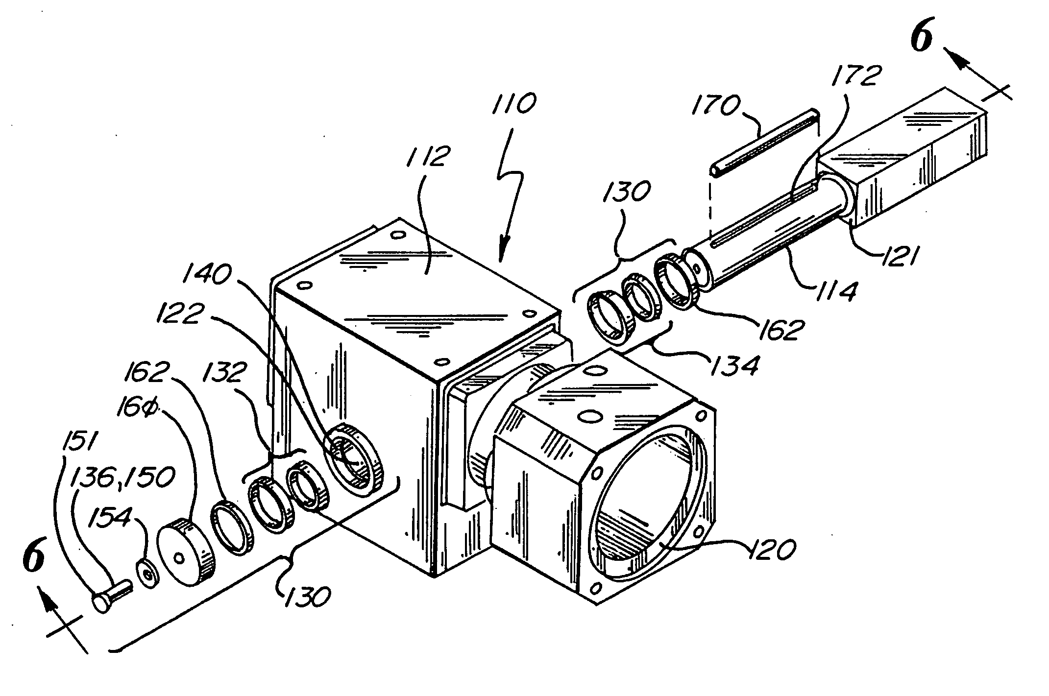
[0033] The present invention is generally shown in the Figures as reference numeral 110.

[0034] The present invention 110 is a gearbox 110 having a housing 112, an input shaft 120, and an output shaft 114 journalled within a hollow bore 122.

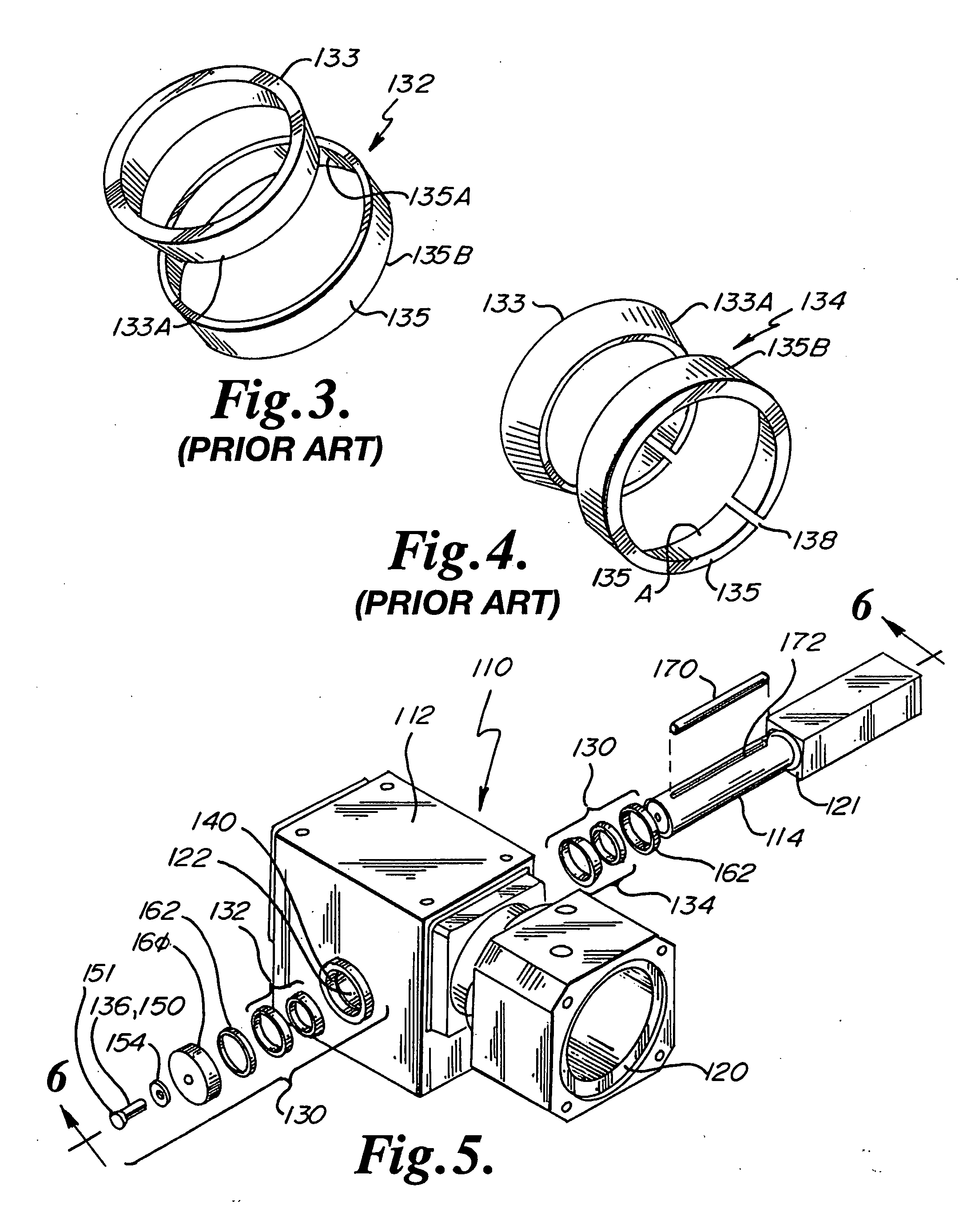
[0035] A backlash reducing apparatus 130 comprises a first pair 132 of interlocking rings engaging the shaft 114 within the hollow bore 122 at one end of the hollow bore 122; a second pair 134 of interlocking rings engaging the shaft 114 at the opposite end of the hollow bore 122; and a fastener 136 engaging the shaft 114 and applying axial pressure to the first 132 and second 134 pairs of interlocking rings to thereby force the first 132 and second 134 pairs of interlocking rings against the shaft 114 and hollow bore 122.

[0036] As shown in FIGS. 3 and 4, the pairs 132 and 134 of interlocking rings comprise an inner ring 133 and an outer ring 135. The outer ring 135 is tapered on its inner surface 135A, as shown; and the inner ring 133 is taper...


PUM


Abstract

A backlash reducing apparatus for a gearbox, the gearbox having a hollow bore and a shaft in the hollow bore, with the hollow bore having a counter-bore at each end includes: a first pair of tapered, interlocking rings engaging the shaft within the hollow bore at one end of the hollow bore; a second pair of tapered, interlocking rings engaging the shaft within the hollow bore at the opposite end of the hollow bore; and a fastener engaging the shaft and applying axial pressure to the first and second pairs of tapered, interlocking rings to thereby force the first and second pairs of tapered, interlocking rings against the shaft and the hollow bore. A method for reducing backlash in a gearbox, the gearbox having a hollow bore and a shaft in the hollow bore, consists of: engaging a first pair of tapered, interlocking rings against the shaft within the hollow bore at one end of the hollow bore; engaging a second pair of tapered, interlocking rings against the shaft within the hollow bore at the other end of the hollow bore; and applying axial pressure to the first and second pairs of tapered, interlocking rings to thereby force the first and second pairs of tapered, interlocking rings against the shaft and the hollow bore.

Description

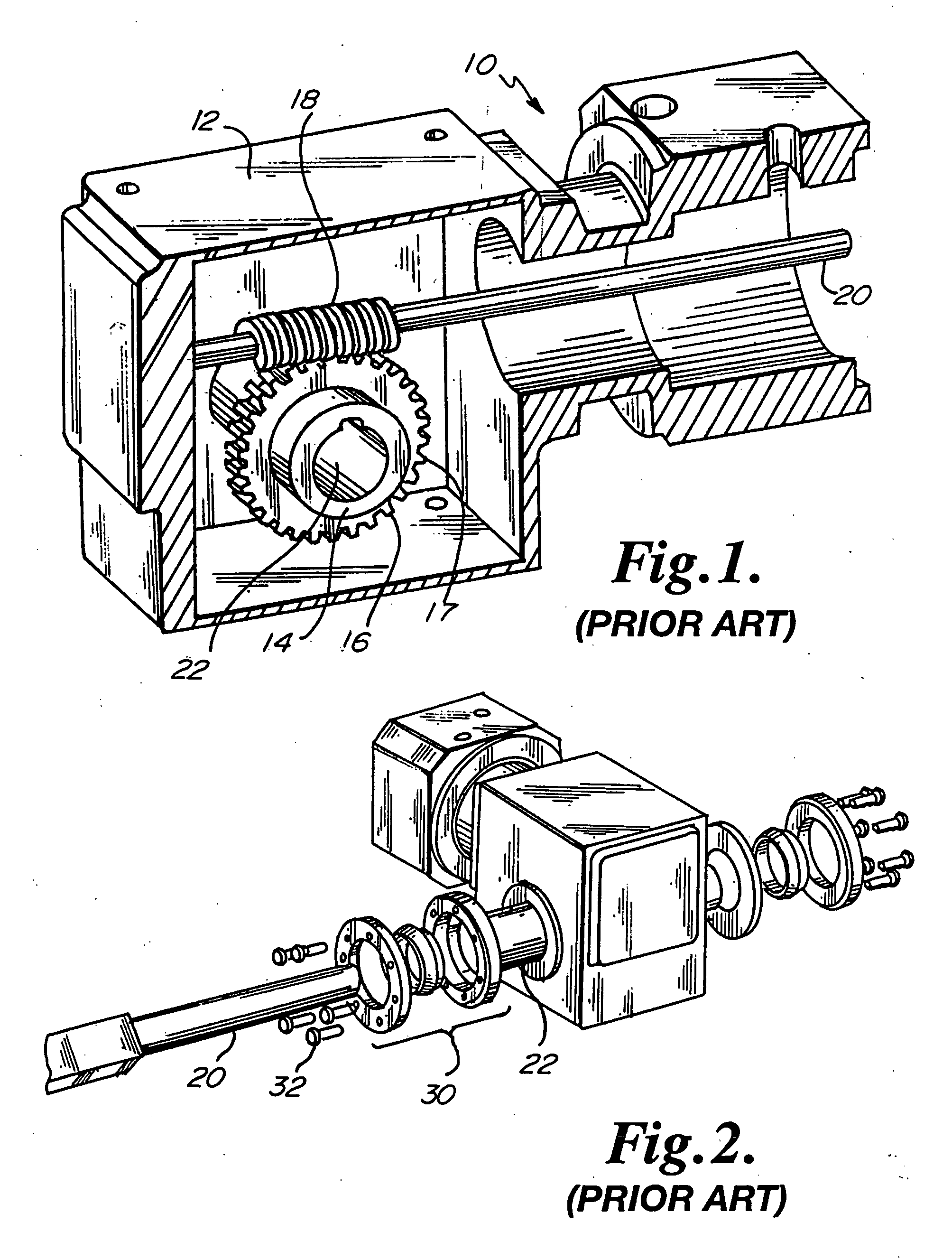
BACKGROUND OF THE INVENTION [0001] The present application is related to a backlash reducing mechanism for a gearbox or the like, and in particular to a backlash reducer that incorporates opposed pairs of interlocking, tapered rings at opposite ends of the gearbox hollow output shaft. [0002] Mechanical loss motion (resulting from backlash) is of concern in servo drive line components; positioning errors, changes to systems dynamics, and mechanical component failures are all attributed to system backlash. To minimize loss motion designers look for ways to reduce or completely eliminate the backlash in each component in the system. This can affect the economy of the design, or introduce added complexity that may make implementation impossible. [0003]FIG. 1 is a schematic of a hollow bore output gearbox 10 with a housing 12. This particular drawing shows a worm design for clarity. An output gear 16 incorporates a hollow bore 22 through hub 14. A periphery of gear teeth 17 engage the wo...

Claims


Application Information

Patent Timeline
Patent Type & Authority Applications(United States)
IPC IPC(8): F16H55/18
CPCF16D1/094Y10T74/19623F16H57/021
Inventor LUKANEN, RICHARD W. JR.
Owner DOUGLAS MACHINE LIABILITY
Learn More