Method and apparatus for generating a serial clock without a PLL

a serial clock and clock technology, applied in the field of data transmission, can solve the problems of large chip real estate, large power consumption of pll's, complex structure, etc., and achieve the effects of reducing design time, reducing complexity of pll's design, and reducing power dissipation

Inactive Publication Date: 2007-03-15
SEMICON COMPONENTS IND LLC
View PDF37 Cites 3 Cited by
  • Summary
  • Abstract
  • Description
  • Claims
  • Application Information

AI Technical Summary

Benefits of technology

[0015] The present invention provides a method and apparatus demonstrating low power dissipation and an efficient die size circuit for sending data serially. It also reduces design time by eliminating complexity of designing PLL's, while eliminating the lock time required by PLL's.

Problems solved by technology

But, PLL's consume significant power, are complex, require long locking times, and occupy considerable chip real estate.
This approach is limited by requiring an accurate one-shot set up and then the use of a set bit clock that cannot change.
These parallel drivers consume high power and output high currents that create significant system noise.
In the newer designs, using sixty-four and one hundred and twenty-eight bits, the pins available on the packages become a design limitation.
However, the problem persists.
Up to the present time, serializing and de-serializing data entails using PLL's that are complex and costly of power chip space and time, as discussed above.

Method used


Image

  • Method and apparatus for generating a serial clock without a PLL
  • Method and apparatus for generating a serial clock without a PLL
  • Method and apparatus for generating a serial clock without a PLL

Examples


Embodiment Construction

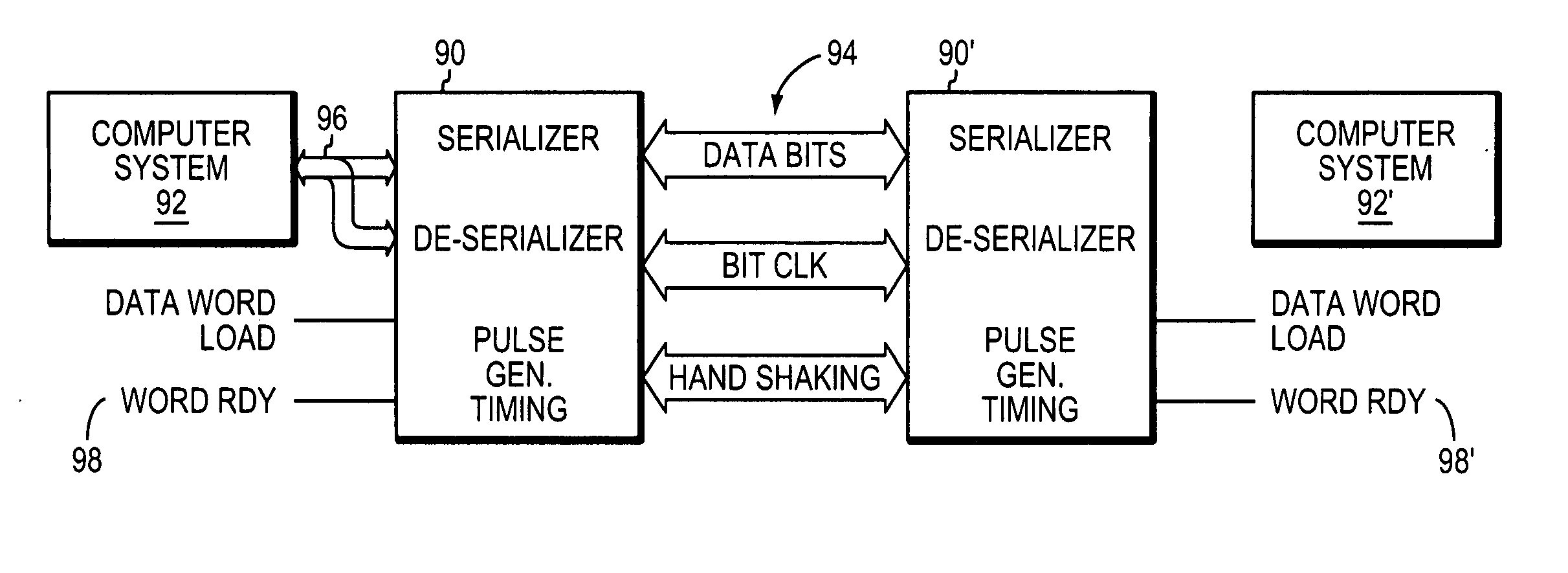
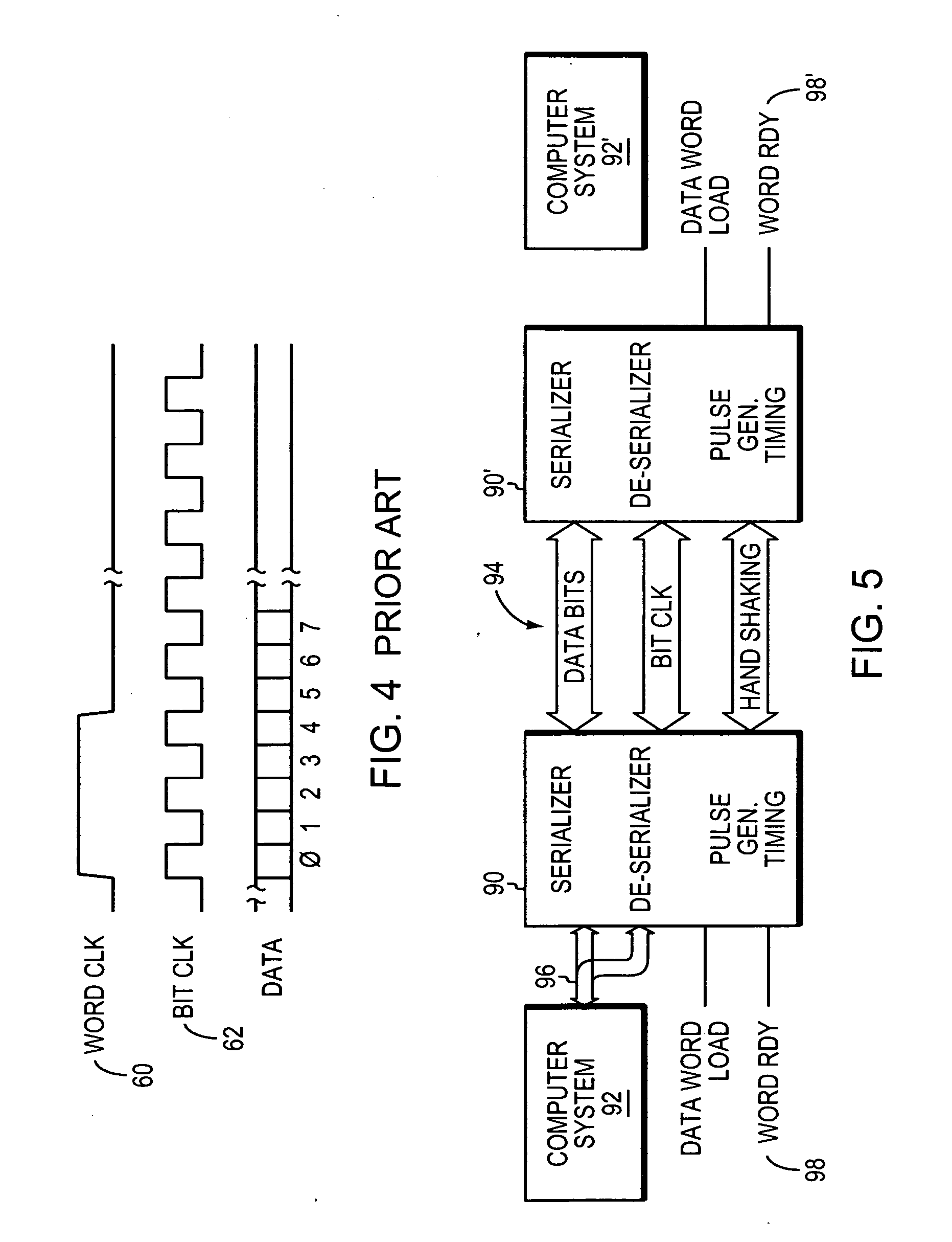
[0034] Practitioners in the art know that many variations of the system illustrated in FIG. 5 are possible. The following descriptions are illustrative and those practitioners in the art will know of, or develop, other configurations that may advantageously use the present invention.

[0035]FIG. 5 shows computer systems 92 and 92′ that may be virtually any electronic systems where parallel data is available for reading or writing. That is, besides usual computer systems, camera electronics, memory electronics, keyboards, scanners, print heads, wireless communications, etc., are among other such systems known in the art that may employ the present invention.

[0036] Most practical systems that may use the present invention, will typically employ “handshaking” signals to indicate the status of a data receiver or sender. Some systems, however, may simply send out data continuously at a regular rate without using any handshaking. For example, handshaking signals may be used to control whi...


PUM


Abstract

A clock circuit for outputting serial data without using a PLL is described. The clock is a VCO designed to start at a frequency that is slightly higher than necessary to preserve the data. The frequency of the clock is measured and if the frequency is too high or too low the DC control voltage for the VCO is changed to bring the VCO frequency back to the start frequency. Clock counters, holding registers, comparators, and a D/A form a feed back path around a VCO. In addition, a word boundary generator is used to define individual data words. The word boundary is formed by the absence of a bit clock transition while there is a data bit transition. A high/low threshold may be used where the VCO frequency, as measured, must transcend a threshold before the DC control voltage to the VCO is changed.

Description

CROSS REFERENCE TO RELATED APPLICATIONS [0001] This application is related to commonly owned, U.S. applications, Ser. No. 10 / 802,372, filed Mar. 16, 2004 entitled ARCHITECTURE FOR BIDIRECTIONAL SERIALIZERS AND DESERIALIZERS; Ser. No. 10 / 802,436, filed Mar. 16, 2004 entitled BIT CLOCK WITH EMBEDDED WORD CLOCK BOUNDARY and Ser. No. 10 / 824,747, filed Apr. 15, 2004 entitled SENDING AND / OR RECEIVING SERIAL DATA WITH BIT TIMING AND PARALLEL DATA CONVERSION. These applications are incorporated herein by reference.BACKGROUND OF THE INVENTION [0002] 1. Field of the Invention [0003] The present invention relates to data transmission, and more particularly to serializing and sending, bit by bit, a data word and a bit clock with an embedded data word boundary. [0004] 2. Background Information [0005]FIG. 1 illustrates a known serializer in a block schematic form. A parallel data word 10 is loaded into a buffer register 12 with a word clock 14. The word clock 14 is also fed to a phase locked loop...

Claims


Application Information

Patent Timeline
Patent Type & Authority Applications(United States)
IPC IPC(8): H03M9/00
CPCH03M9/00G06F1/08
Inventor MORRILL, DAVID P.
Owner SEMICON COMPONENTS IND LLC
Why Eureka
Try Eureka