Method and a system for control of a device for compression

a control system and compression device technology, applied in the field of com, can solve the problems of insufficient droplets, inability to prove any decrease of work, and inability to make sufficiently small droplets, so as to reduce the compression work in such a compressor or combustion engin

Inactive Publication Date: 2007-07-05
CARGINE ENG AB
View PDF10 Cites 64 Cited by
  • Summary
  • Abstract
  • Description
  • Claims
  • Application Information

AI Technical Summary

Benefits of technology

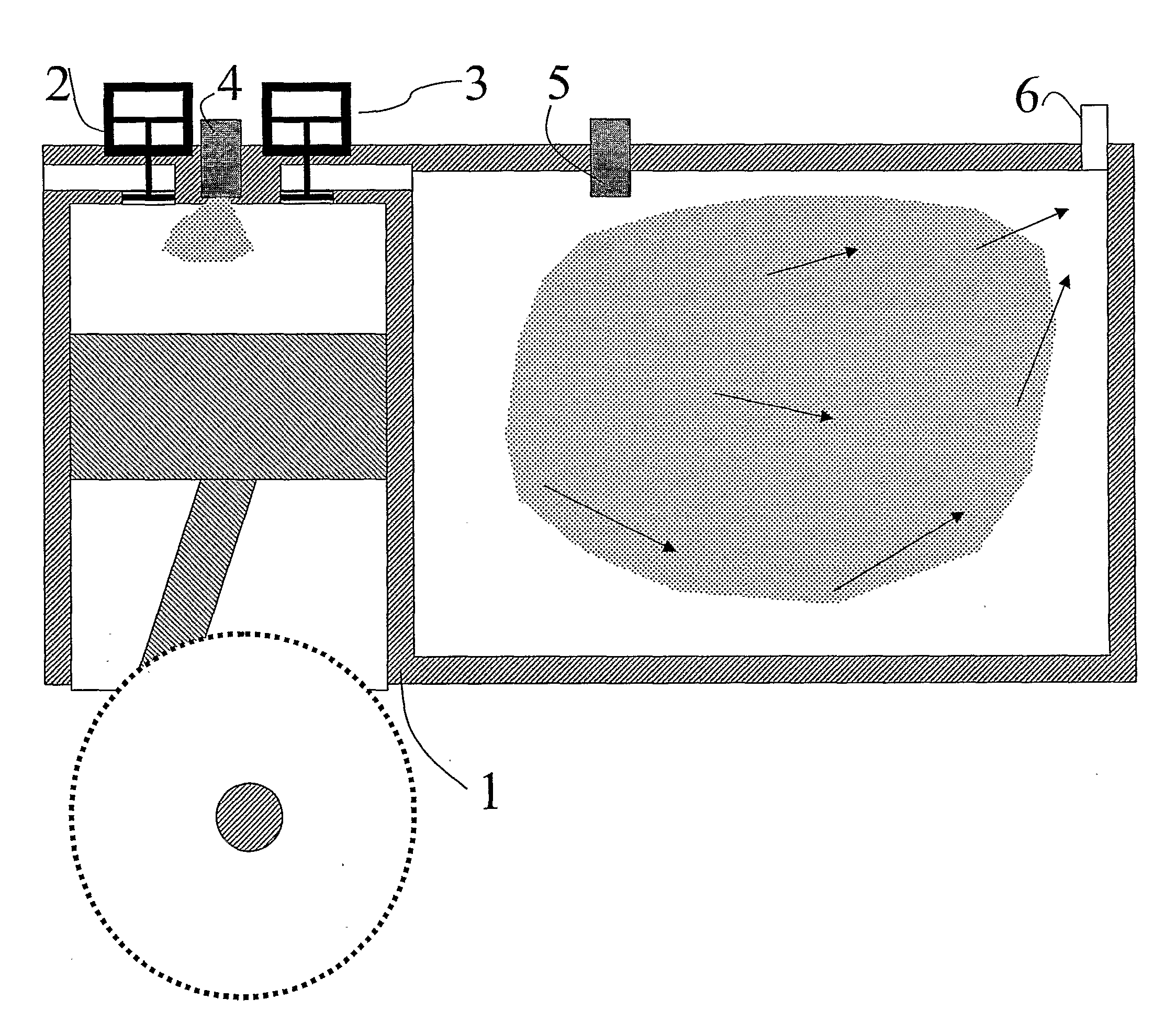
[0011] The object of the present invention is to solve the problems mentioned above by defining a new method that defines a principal which is applicable for the injection of water during compression into the compression chamber of combustion engines and compressors, for the purpose of decreasing the compression work in such a compressor or combustion engine.
[0012] Accordingly, the invention should result in that the water that is used as an injection medium is used in such a way that it increases the efficiency of combustion engines and compressors and reduces the generation of nitrogen oxides in combustion engines. SUMMARY OF THE INVENTION
[0018] An implementation of the present invention will motivate a use of said system commercially for combustion engines. Preferably, the method is possible to use for all types of combustion engines in which the air is compressed. The water that is heated and / or evaporated during the compression and upon the implementation of the invention, absorbs and drains off the compression heat and reduces, accordingly, the compression work, thereby improving the efficiency of the engine. The combustion that follows the compression stroke is initiated with a lower temperature, resulting in a lower maximum temperature and a reduced generation of NOx. However, there is one further temperature-reducing factor, namely that a larger mass, operating medium and water steam, should be heated, instead of only the operating medium, by the energy that is set free during the combustion. Accordingly, the water steam has the same effect as so called EGR, Exhaust Gas Regeneration, which is a common method for the purpose of reducing the generation of NOx through a lower temperature at the combustion. The need of cylinder cooling is reduced, resulting in an improvement of the efficiency. The invention is particularly suitable when hydrogen gas or natural gas is used as fuel, since the recycling of the water is facilitated when the exhaust gases are mainly constituted by water. The method is also suitable upon the compression of, for example, hydrogen gas or natural gas to be used as fuel in combustion engines and in fuel cells.

Problems solved by technology

As a hole, the result of the attempt, was that it was not possible to prove any decrease of work.
This resulted in a need of substantially more water, but, however, the droplets could not be made sufficiently small; in other words, the total cooling surface area, which was the sum of the surfaces of all droplets, was to small.
However, the results have not been good enough to motivate the use of any commercial systems for transporting and / or recycling water from the exhaust gases of the engines.

Method used


Image

  • Method and a system for control of a device for compression
  • Method and a system for control of a device for compression
  • Method and a system for control of a device for compression

Examples


Embodiment Construction

[0027] The principal basis of the invention can be seen in table 1. In column A there is shown some different pressures (bar), by adiabatic compression of air, where the air pressure before compression is 1 bar and the temperature is 273 K. Kappa is 1.4. In column B, the temperature (K) is shown for the compressed air with the different pressures according to column A. In column C the boiling point temperature (K) of the water is shown for the different pressures according to column A. The boiling point temperatures of the water for the different pressures are ocularly retrieved from steam pressure curves. Column D shows the pressurisation which is necessary for preventing the water from boiling at the temperature according to column B.

TABLE 1Different pressures and temperatures during adiabaticcompression of air, and the boiling point temperature of the water atthese pressures. The reference from which the equations for thecalculation of the values at the adiabatic compression, a...


PUM


Abstract

A method of compressing a medium in the combustion chamber of a combustion engine, wherein a liquid spray is introduced into the compression chamber during a compression stroke, the liquid is pressurized and heated before introduction into the compression chamber to such a degree that at least a part of the droplets of the spray explode spontaneously upon entrance in the compression chamber. The pressurized liquid has a steam pressure that is above the pressure in the compression chamber, and the liquid has a temperature that exceeds the boiling point of the liquid for the temperature and the pressure that, at the moment of introduction, exists in the compression chamber, and the heat being water. The liquid is heated to such an extent that, at the moment of introduction, it has a temperature that is below the temperature of the medium at the moment of introduction of the liquid.

Description

TECHNICAL FIELD [0001] The present invention relates to a method of compressing a medium in the combustion chamber of a combustion engine, by which method a liquid, in the state of a spray, is introduced into the compression chamber during a compression stroke and, the liquid is pressurized and heated before it is introduced into the compression chamber to such a degree that at least a part of the droplets of the spray explode spontaneously upon entrance in the compression chamber, the liquid being pressurized to such an extent that, at the moment of introduction, it has a steam pressure that is above the pressure that, at the moment of introduction, exists in the compression chamber, and the liquid being heated to such and extent that, at the moment of introduction, it has a temperature that exceeds the boiling point of the liquid for the temperature and the pressure that, at the moment of introduction, exists in the compression chamber, and the liquid being water. [0002] The inven...

Claims


Application Information

Patent Timeline
Patent Type & Authority Applications(United States)
IPC IPC(8): F02B47/02F02B1/12F04B39/06F02B3/00F02MF02M25/03
CPCF02B47/02F02M25/03F02M25/0224F02M25/0227Y02T10/121
Inventor HEDMAN, MATS
Owner CARGINE ENG AB
Why Eureka
Try Eureka