
Method of manufacturing nano-fibers with excellent fiber formation

Inactive Publication Date: 2007-07-05
FINETEX TECH GLOBAL +1
View PDF3 Cites 28 Cited by
  • Summary
  • Abstract
  • Description
  • Claims
  • Application Information

AI Technical Summary

Benefits of technology

[0011] To solve the above problems, the present invention provides a method for producing nanofibers which is capable of effectively preventing nanofibers collected on a collector from being dissolved again by volatilizing the solvent remaining on the collector more quickly during an electrostatic spinning process.

Problems solved by technology

In the case that nanofibers are produced by such typical electrostatic spinning method of the prior art, there is a problem that the nanofibers collected on the collector are dissolved by a solvent remaining on the collector to thereby greatly deteriorate the fiber formation ability.
Especially, in the case that a solvent with a low volatility (a solvent with a high boiling point) is used, the above-mentioned problem becomes more serious.
Further, even in the case that a solvent with a high volatility (a solvent with a low boiling point) is used, the above-mentioned problem occurs in a manner that, when nanofibers are electrostatically spun for a long time for the purpose of mass production, the solvent remains on the collector, and accordingly the nanofibers collected on the collector are dissolved.
As a result, the typical electrostatic spinning method of the prior art was not appropriate for mass production, and has limitations in the types of utilizable solvents.

Method used


Image

  • Method of manufacturing nano-fibers with excellent fiber formation
  • Method of manufacturing nano-fibers with excellent fiber formation
  • Method of manufacturing nano-fibers with excellent fiber formation

Examples


example 1

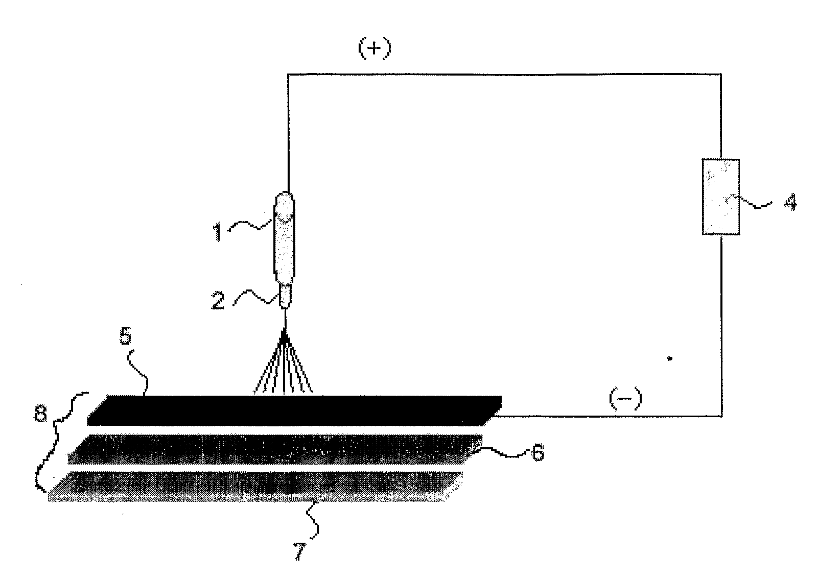
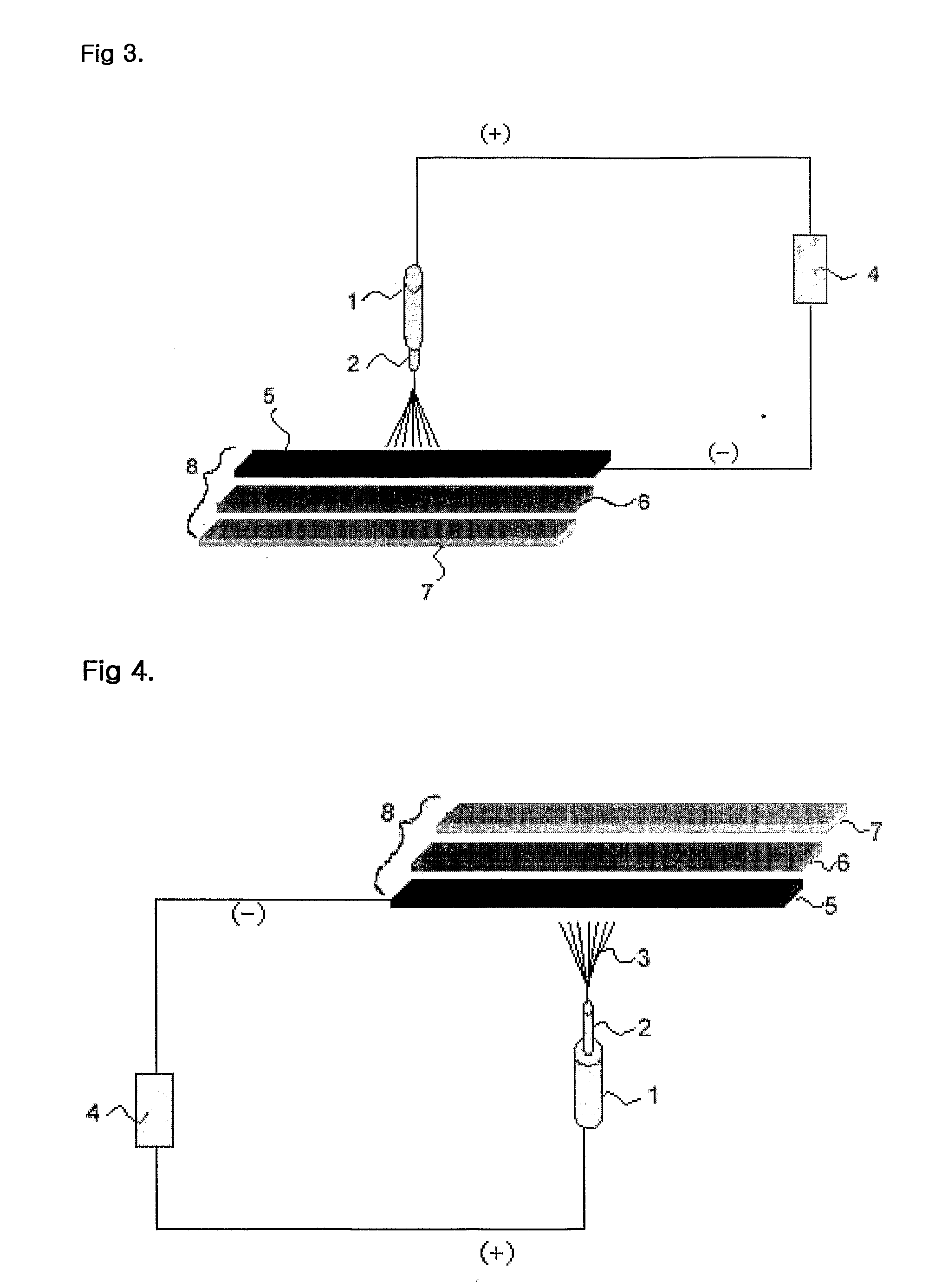
[0056] 8% by weight of polyurethane resin (Pellethane 2103-80AE of Dow Chemical Company) with a molecular weight of 80,000 was dissolved N, N-dimethylformamide to prepare a spinning liquid. Next, the prepared spinning liquid was electrostatically spun in a down-top electrostatic spinning method as shown in FIG. 4 to produce nanofibers.

[0057] During the electrostatic spinning, the voltage was 30 kV and the spinning distance was 20 cm. As a voltage generator, Model CH 50 of Simco Company was used. As a nozzle plate, a nozzle plate with 2,000 holes (nozzles) having a 0.8 diameter uniformly arranged was used.

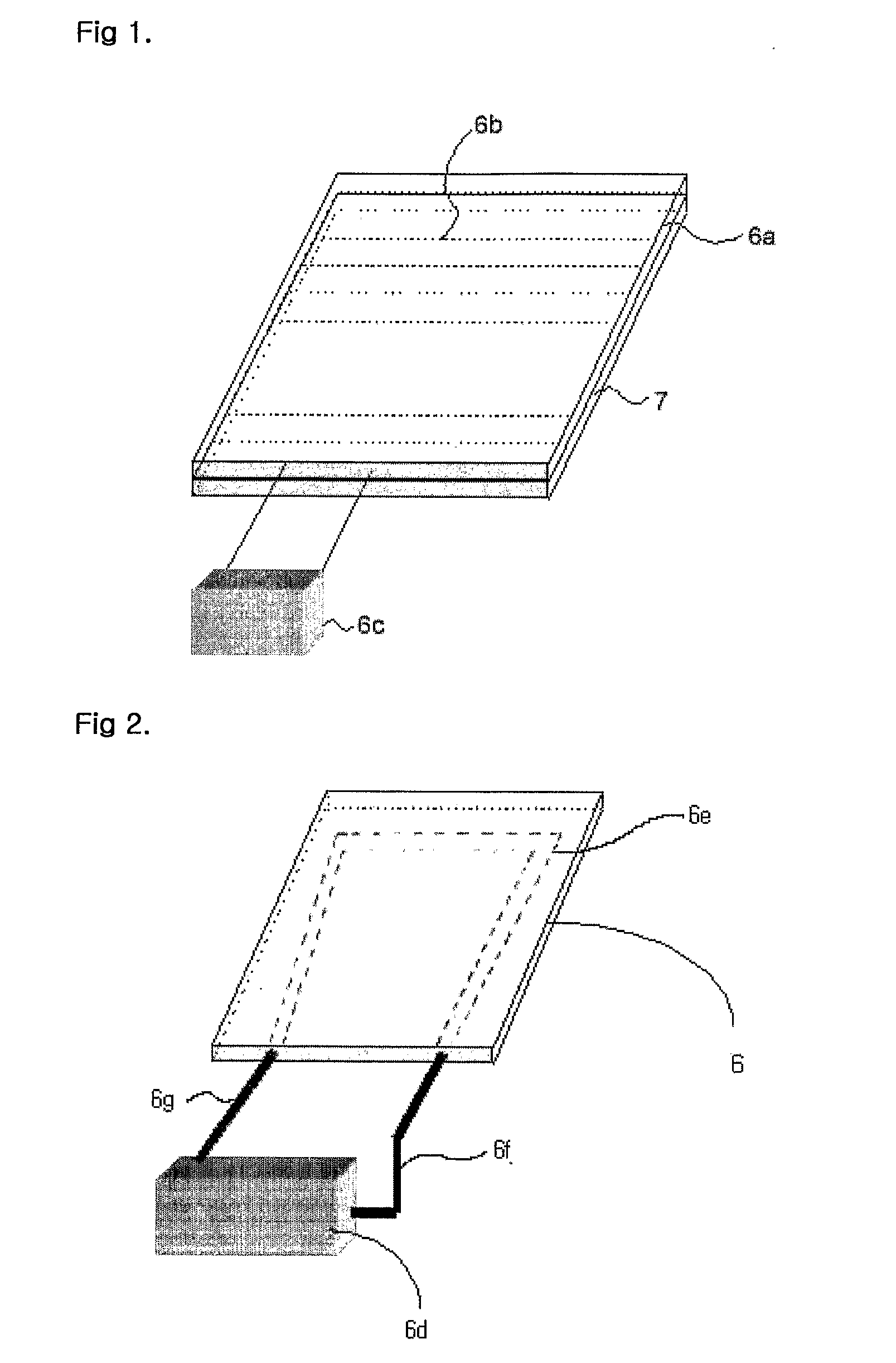
[0058] Further, as a collector 8, was used a laminate element of a three layer structure which is composed of (i) a supporting element 7 of a polypropylene plate, (ii) a heater 6 of direct heating type located on the supporting element and composed of a heating plate 6a which has hot wires 6b covered with silicon arranged at constant intervals and a temperature controller 6c attac...

example 2

[0060] 8% by weight of polyurethane resin (Pellethane 2103-80AE of Dow Chemical Company) with a molecular weight of 80,000 was dissolved N, N-dimethylformamide to prepare a spinning liquid. Next, the prepared spinning liquid was electrostatically spun in a down-top electrostatic spinning method as shown in FIG. 4 to produce nanofibers.

[0061] During the electrostatic spinning, the voltage was 30 kV and the spinning distance was 20 cm. As a voltage generator, Model CH 50 of Simco Company is used. As a nozzle plate, a nozzle plate with 2,000 holes (nozzles) having a 0.8 diameter uniformly arranged was used.

[0062] Further, as a collector 8, was used a laminate element of a three layer structure which is composed of (i) a supporting element 7 of a polypropylene plate, (ii) a heater 6 of such a plate type that has a heat transfer medium circulation tube 6e equipped inside and is connected to a circulation type heat reservoir 6d by a heat transfer medium feed section 6f and a heat transf...


PUM

PropertyMeasurementUnit
Massaaaaaaaaaa
Temperatureaaaaaaaaaa
Thicknessaaaaaaaaaa

Abstract

The present invention relates to a method for producing nanofibers with an excellent fiber formation property, characterized in that: when nanofibers 3 having a thickness of a nano level are produced by electrostatically spinning a spinning liquid 1 of a polymer resin solution on a collector 8 through a nozzle 2 under a high voltage, a collector 8 with a heater is used as the collector. The present invention can greatly improve the fiber formation property of the nanofibers.

Description

TECHNICAL FIELD [0001] The present invention relates to a method for producing fibers having a thickness of a nano level (hereinafter, ‘nanofibers’), and more specifically to a method for producing nanofibers which is capable of effectively preventing nanofibers collected on a collector from being dissolved again by a remaining solvent, especially a solvent with a low volatility (a solvent with a high boiling point) to thus deteriorate fiber formation property by quickly volatilizing the solvent remaining on the collector using the collector with a heater. [0002] More concretely, the present invention relates to a method capable of mass production of nanofibers at a high efficiency since remaining solvents can be volatilized more efficiently so that nanofibers electrostatically spun and collected on a collector are not dissolved again by the solvents remaining on the collector when nanofibers are produced by using a solvent with a low volatility (a solvent with a high boiling point)...

Claims


Application Information

Patent Timeline
IPC IPC(8): H05B7/00D01D5/00D01D5/26D01F6/70
CPCD01D5/0076D01F6/70D01D7/00
Inventor KIM
Owner FINETEX TECH GLOBAL
Learn More