
Interleaved and directional wireless mesh network

a wireless mesh network and interleaved technology, applied in the field of wireless mesh networks, can solve the problems of significant bandwidth limitation, complex and difficult to deal with the mesh network where the channel change from hop to hop is complicated, and the architecture of fig. 1(i>b/i>) suffers from performance limitations, so as to improve the performance of the highest priority packet stream

Active Publication Date: 2007-07-05
CALLAHAN CELLULAR L L C
View PDF53 Cites 35 Cited by
  • Summary
  • Abstract
  • Description
  • Claims
  • Application Information

AI Technical Summary

Benefits of technology

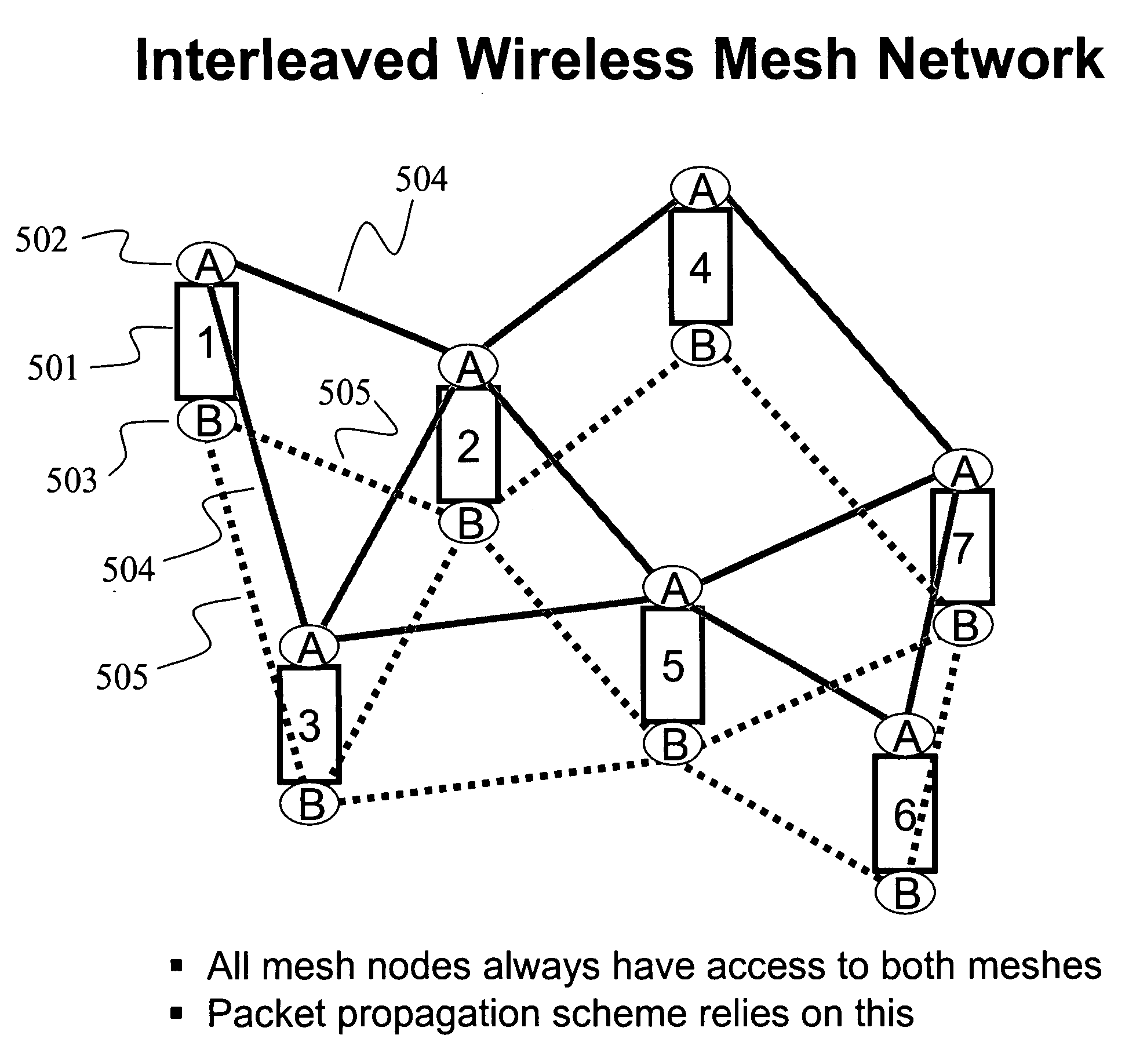
[0019]An interleaved mesh is described that uses at least two relay radios on each node to create two or more simultaneous mesh networks, each on separate channels. A transmitted stream of packets will then utilize any or all of these multiple simultaneous meshes as they propagate through the overall mesh network. For any particular hop, a packet may use any of the available meshes to propagate to the next node. From hop to hop, a particular packet may change which mesh it travels on to reach the next node. Here, two sequential packets in a particular packet stream may travel on the same mesh or on different meshes for any given hop. Two sequential packets can even be transmitted simultaneously from a first node to a second node. Thus, a single stream of sequential packets may be transmitted between two mesh nodes at twice the speed that would normally occur if only a single link were used, or even if multiple links were used but limited to propagating unique streams of packets separately on each link. Therefore, the performance of the highest priority packet stream will be improved regardless of whether traffic loading in the mesh is high or low at the time of transmission.
[0020]When two radios are used on a particular node for packet relay according to an interleaved mesh per this invention, data can be received on one radio while simultaneously being sent on the other radio. This circumvents the limitations of a single radio system without requiring complex channel management schemes, while at the same time providing a mesh that can easily operate without a server or internet connection—critically important for Public Safety applications when isolated First Responders are separated from their backhaul connection and must communicate among themselves.
[0021]To take advantage of the low cost of commonly available radio cards while compensating for their relatively low power and receive sensitivity, a mesh architecture is also described where a relatively large number of radios is used with multiple directional or sector antennas, or multi-element directional antennas, such that radiated energy is effectively focused. This is particularly useful in urban applications where the relay or backhaul path between nodes must travel between tall buildings, a narrow beam directional or sector antenna being most efficient for the task. This directional mesh architecture is designed as shown such that it is compatible with the interleaved mesh described earlier, thus facilitating a Public Safety mesh that supports both fixed nodes (with directional or sector antennas) and mobile nodes (with omni antennas) where the mobile nodes can be man-carried or mounted on vehicles.

Problems solved by technology

This causes a significant bandwidth limitation since a single radio cannot send and receive at the same time.
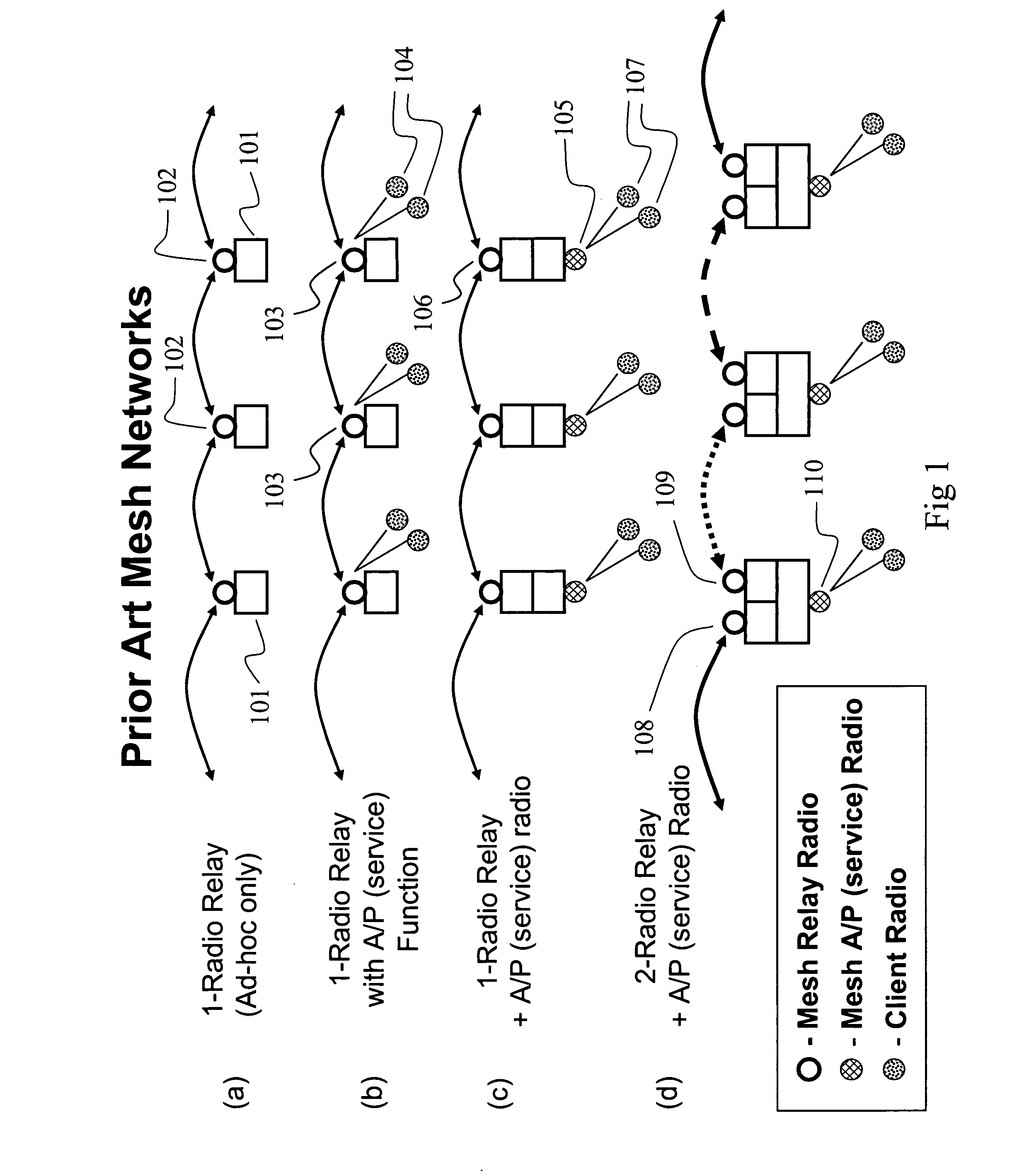
The architecture of FIG. 1(b) suffers from performance limitations since the single radio must not only relay packets, but also service numerous client radios 104 at each node.
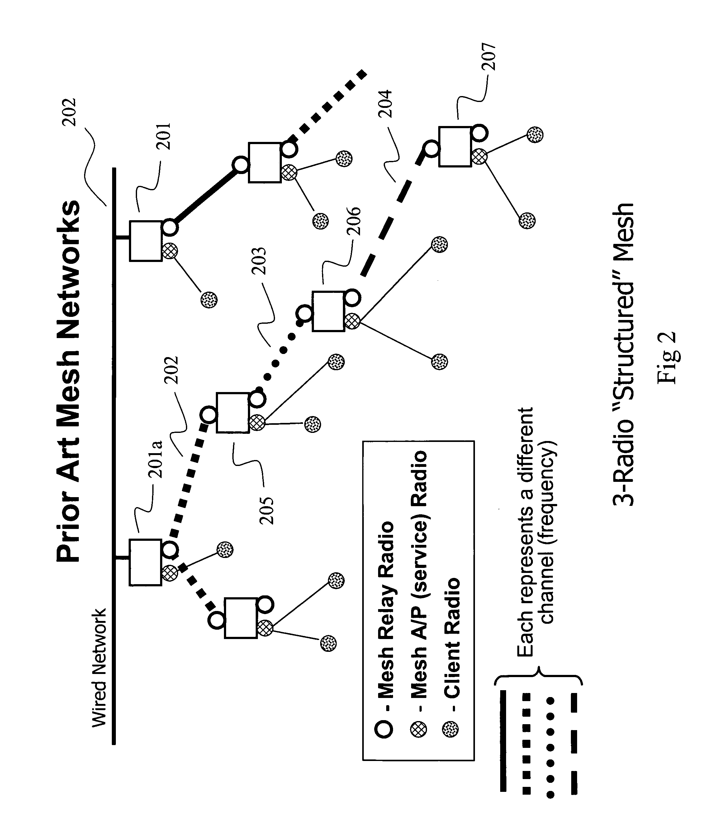
In this type of mesh network, the mesh control software on each node has a significant challenge in assigning the various available channels throughout the mesh such that interference effects are minimized, and the mesh functions properly.
Either way, having a mesh network where channels change from hop to hop is complicated and difficult to deal with.
In the case of a public safety mesh with mobile nodes (for vehicles and individual First Responders on foot), a further problem arises with this form of mesh.
For instance, if a group of first responders each carrying a mesh node become isolated from the backhaul connection to the server (Command and Control), the tree-like structure of FIG. 2 may become compromised since there is no longer a defined root for the tree.
e). Also, when connections between nodes must change because of a node failure, temporary disturbances to the mesh (moving obstacles or radar interference), node movement, or QOS considerations, there can be a ripple effect of changing channels causing even greater com
However, the solution does not integrate any additional functionality beyond what is shown in FIG. 4, and from a performance standpoint, each of the two individual mesh networks embodied here will have the performance restrictions of other prior art mesh architectures constructed according to FIG. 1(c).
While some mesh vendors claim to have installed mesh networks in hundreds of cities, all but a few of these are suburban towns, not large cities with tall buildings.
In fact, none of the mesh systems offered today have been designed to handle the problems encountered in the depths of larger cities where high rise buildings create a “concrete canyon” effect.
When today's mesh nodes are deployed in such situations, much of the energy radiated from their omni-directional antennas is reflected and / or wasted.
Other factors involved in mesh node and mesh architecture design involve both the transmit power and cost of radio cards.
Frequencies in the 700 MHz to 900 MHz range have great penetration and range capabilities, but are prone to adjacent channel interference.

Method used


Image

  • Interleaved and directional wireless mesh network
  • Interleaved and directional wireless mesh network
  • Interleaved and directional wireless mesh network

Examples


Embodiment Construction

[0059]The invention is illustrated by way of example and not by way of limitation in the figures of the accompanying drawings in which like references indicate similar elements. References to embodiments in this disclosure are not necessarily to the same embodiment, and such references mean at least one. While specific implementations are discussed, it is understood that this is done for illustrative purposes only. A person skilled in the relevant art will recognize that other components and configurations may be used without departing from the scope and spirit of the invention.

[0060]In the following description, numerous specific details are set forth to provide a thorough description of the invention. However, it will be apparent to those skilled in the art that the invention may be practiced without these specific details. In other instances, well-known features have not been described in detail so as not to obscure the invention.

[0061]One of the key components of the present inv...


PUM


Abstract

A directional and interleaved wireless mesh network is described where mesh nodes have directional antennas facing in horizontally orthogonal directions. The antennas can be focused to have a beam width of less than ninety degrees in order to achieve greater strength of signal and radiation. Each mesh node can have two radios that communicate on separate channels, such that packets propagated through the mesh network can utilize either channel in order to hop from one node to the next. Each radio can be connected to four orthogonally directed antennas in order to enable communication with adjacent nodes. Alternatively, a separate independent radio can be connected to each antenna in order to achieve greater simultaneity of transmission and reception to the node. For example, two such radio-antenna combinations can be facing in each of the four orthogonal directions, each of the two combinations operating on a different RF channel.

Description

COPYRIGHT NOTICE[0001]A portion of the disclosure of this patent document contains material which is subject to copyright protection. The copyright owner has no objection to the facsimile reproduction by anyone of the patent document or the patent disclosure, as it appears in the Patent and Trademark Office patent file or records, but otherwise reserves all copyright rights whatsoever.CLAIM OF PRIORITY[0002]This application claims the benefit and priority of U.S. Provisional Application Ser. No. 60 / 756,794, filed on Jan. 5, 2006, and entitled “DIRECTIONAL AND INTERLEAVED WIRELESS MESH NETWORKS,” commonly assigned with the present application and incorporated herein by reference.CROSS REFERENCES TO RELATED APPLICATIONS[0003]This application is related to and cross references the following U.S. patent applications, which are incorporated herein by reference:[0004]U.S. patent application No. entitled “INTERLEAVED WIRELESS MESH NETWORK,” by Robert Osann, Jr., filed on Aug. 11, 2006, Att...

Claims


Application Information

Patent Timeline
IPC IPC(8): H04L12/56H04L12/28
CPCH04W88/04H04W84/00
Inventor OSANN, ROBERT
Owner CALLAHAN CELLULAR L L C
Learn More