Rotary cutting tool

a cutting tool and rotary technology, applied in the direction of adverse effect compensation, metal-working equipment, milling equipment, etc., can solve the problems of reducing the useful life of the product,

Active Publication Date: 2007-07-05
KYOCERA SGS PRECISION TOOLS INC
View PDF11 Cites 68 Cited by
  • Summary
  • Abstract
  • Description
  • Claims
  • Application Information

AI Technical Summary

Benefits of technology

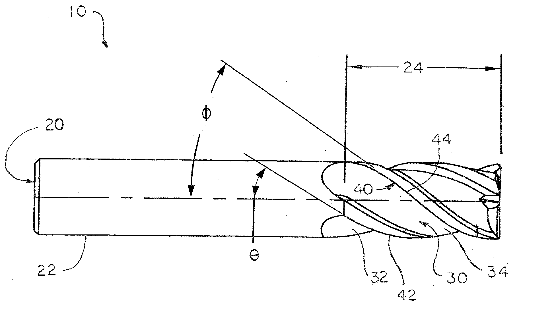
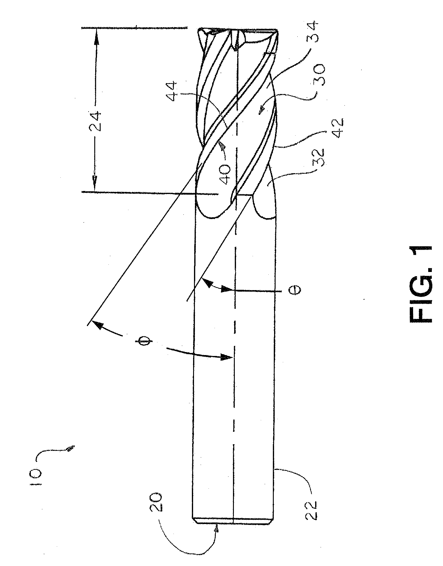
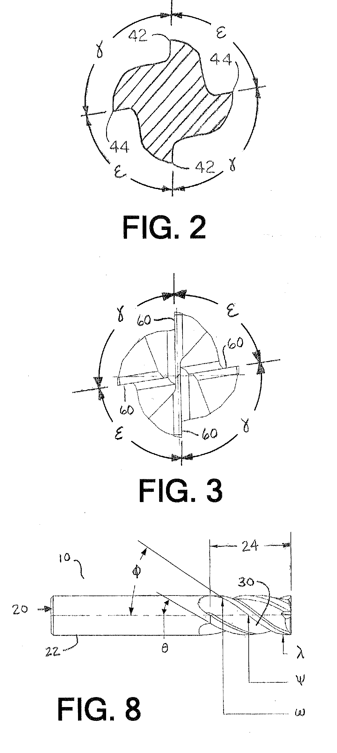
[0010] The present invention overcomes at least one disadvantage of the prior art by providing A rotary cutting tool comprising: a body having a cutting portion and a shank portion; a plurality of pairs of diametrically-opposed, symmetrical, helical flutes formed in the cutting portion of the body, wherein the pitch between at least one pair of adjacent helical flutes is less than or greater than the pitch of at least one other pair of adjacent helical flutes in at least one radial plane along the axial length of the flutes; a plurality of peripheral cutting edges associated with the plurality of the helical flutes; wherein at least one of the peripheral cutting edges has a radial rake angle different from radial rake angle of a peripheral cutting edge of a different helical flute.

Problems solved by technology

A common problem encountered in the use of end mills is “chatter”.
The self-exciting chatter is usually accompanied by a loud and excessive noise while machining.
Excessive chatter can result in a poor surface finish, rework or scrap of the work product.
Chatter can damage the cutting edge of an end mill and limit its useful life, thereby increasing costs for the milling operation and generating less precise machined parts than may be desired or required for a particular final function.
Excessive chatter can also cause premature wear to the actual milling machine and its components.
It would seem to follow that a tool having everything different would be the best performer in terms of the reduction of chatter, however, testing of these tools have shown a decrease in performance in comparison to other leading end mills.
An end mill having all different features can have stability problems that may be even worse than the problems with chatter.
Another problem with such tools is that the production and resharpening of the tool is difficult because all of the features of the end mill are different.
Like the other prior art end mill discuss above, the testing of this tools has shown a decrease in performance in comparison to other leading end mills, including in the reduction of harmonics.
The reduction of harmonics is not accomplished by making all features different in a random manner as this may have serious adverse consequences with the performance of the tool.

Method used


Image

  • Rotary cutting tool
  • Rotary cutting tool
  • Rotary cutting tool

Examples


Embodiment Construction

[0045] Testing in the form of a sound comparison and a surface finish comparison were conducted to compare the end mill of the present invention with a standard variable helix Z-Carb® end mill and also an end mill made in accordance with U.S. Pat. No. 6,997,651 having different axial rake angles and different radial rake angles, but with equal index angles and helix angles. The three end mills each were made of cemented carbide and having four flutes and a tool diameter of 0.5 inch. A chart comparison of radial rake angles and helix angles is shown below and identified by position on a four flute end mill:

SGS Z-CarbRakeHelixTooth No. 17°35°Center CuttingTooth No. 27°38°Non-Center CuttingTooth No. 37°35°Center CuttingTooth No. 47°38°Non-Center Cutting

[0046]

present inventionRakeHelixTooth No. 13°35°Center CuttingTooth No. 28°38°Non-Center CuttingTooth No. 33°35°Center CuttingTooth No. 48°38°Non-Center Cutting

[0047]

6,997,651RakeHelixTooth No. 1 6°40°Center CuttingTooth No. 215°40°Non...


PUM

PropertyMeasurementUnit
helix angleaaaaaaaaaa

Abstract

A rotary cutting tool or end mill is provided, the tool comprising a plurality of pairs of diametrically-opposed, symmetrical, helical flutes formed in a cutting portion of the tool body, wherein the pitch between at least one pair of adjacent helical flutes is less than or greater than the pitch of at least one other pair of adjacent helical flutes in at least one radial plane along the axial length of the flutes, a plurality of peripheral cutting edges, wherein at least one of the peripheral cutting edges has a radial rake angle different from radial rake angle of a peripheral cutting edge of a different helical flute.

Description

[0001] This application claims the benefit of U.S. provisional patent application 60 / 766,241, filed Jan. 4, 2006, and hereby incorporated by reference.TECHNICAL FIELD [0002] The present invention relates to a rotary cutting tool, and more particularly to an end mill having a plurality of pairs of diametrically-opposed, symmetrical, helical flutes, wherein the pitch between at least one pair of adjacent helical flutes is less than or greater than the pitch of at least one other pair of adjacent helical flutes in at least one radial plane along the axial length of the flutes, a plurality of peripheral cutting edges associated with the plurality of the helical flutes wherein at least one of the peripheral cutting edges has a radial rake angle different from radial rake angle of a peripheral cutting edge of a different helical flute. The improved end mill provides reduced chatter, improved surface finish, and other additional benefits. BACKGROUND OF THE INVENTION [0003] Rotational end m...

Claims


Application Information

Patent Timeline
Patent Type & Authority Applications(United States)
IPC IPC(8): B23C5/10
CPCB23C5/10B23C2210/0414B23C2210/0485B23C2210/0492B23C2210/203B23C2210/282Y10T407/1966B23C2250/16Y10T407/1948Y10T407/1962Y10T407/1958Y10T407/1946Y10T409/303752B23C2210/325
Inventor WELLS, JASON S.DANIELS, PAUL S.BONFIGLIO, DOUGLAS P.BURTON, JEFFERY L.
Owner KYOCERA SGS PRECISION TOOLS INC
Why Eureka
Try Eureka