Extreme UV radiation source device

Active Publication Date: 2007-07-12
USHIO DENKI KK
View PDF15 Cites 43 Cited by
  • Summary
  • Abstract
  • Description
  • Claims
  • Application Information

AI Technical Summary

Benefits of technology

[0061] The invention was devised to eliminate the aforementioned disadvantages in the prior art. In particular, a primary object of the present invention is to devise an EUV radiation source device in which the pumping device located on the side of the dis

Problems solved by technology

The discharge electrodes are therefore exposed to a high thermal load as a result of the discharge.
The metallic debris damages the EUV collector optics and adversely affects the EUV radiation reflection factor of the EUV collector optics.
Because of this, the discharge which forms between the discharge electrodes gradually becomes unstable.
As a result, also the generation of the EUV radiation becomes unstable.
The state in which a discharge forms outside the vicinity of the laser-irradiated area leads to an increase of the thermal load on the electrodes.
Furthermore, the discharge becomes unstable in the vicinity of the laser-irradiated area, by which the EUV output also becomes unstable.
This pu

Method used


Image

  • Extreme UV radiation source device
  • Extreme UV radiation source device
  • Extreme UV radiation source device

Examples


Embodiment Construction

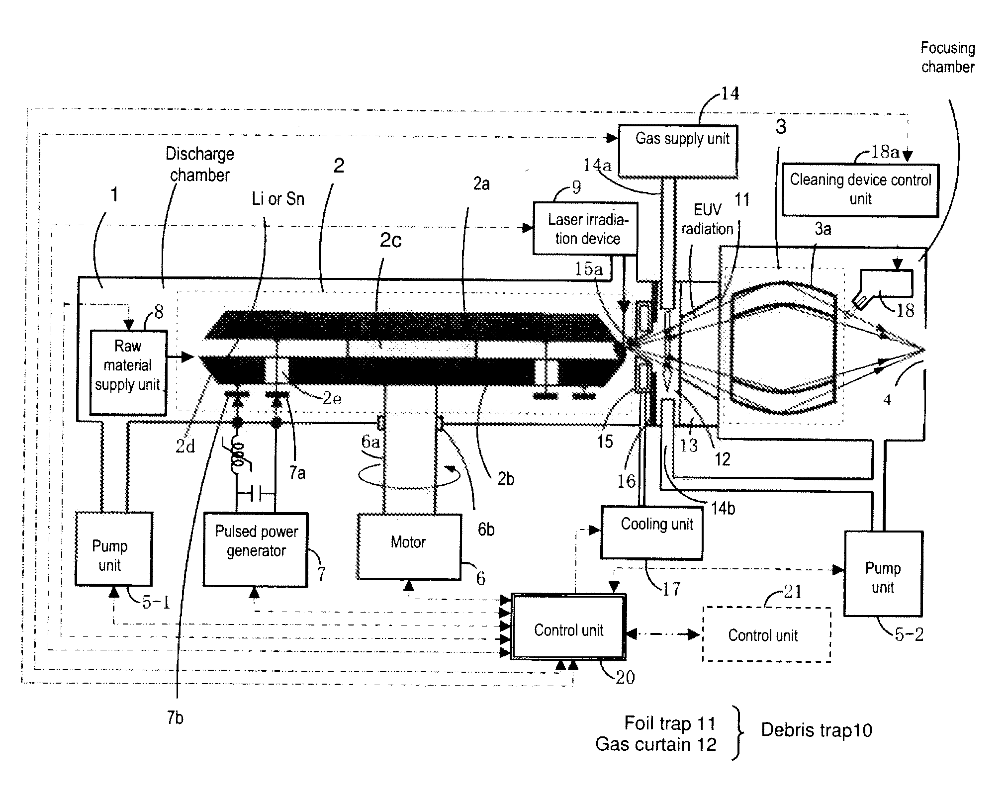
[0103]FIG. 1 shows the arrangement of one embodiment of an EUV radiation source device of the DPP type in accordance with the invention. In the radiation source device of the DPP type in accordance with the invention, the chamber 1 is divided via a partition 16 with an opening essentially into two spaces. That is, in one of the spaces, a discharge part 2 is positioned, while in the other space, an EUV radiation collector part 3 and a debris trap 10 (formed of foil trap 11 and gas curtain 12) are positioned, as is shown in FIG. 1. FIG. 1 shows a case in which an aperture component 15 with an opening 15a is attached to the partition 16. A coolant is supplied to the aperture part 15 from a cooling unit 17, by which the aperture component 15 is cooled.

[0104]FIG. 1 also shows the partition 16 and the aperture component 15 as separate bodies. However, by forming the aperture in the partition 16, the partition 16 can be used as the aperture component. In this embodiment, the debris trap 1...


PUM


Abstract

An EUV radiation source device with a chamber that is divided into a discharge space and a collector mirror space provided with EUV collector optics 3a. Between them an aperture component with an opening which is cooled is provided. First and second discharge electrodes are rotated. Sn or Li is irradiated with laser . Pulsed power is applied between the first and second discharge electrodes to form a high density and high temperature plasma between the two electrodes so that EUV radiation with a wavelength of 13.5 nm is emitted, is focused by the EUV collector optics and is guided into the irradiation optical system of an exposure tool. There are a first pumping device and a second pumping device for pumping the discharge space and the collector mirror space. The discharge space is kept at a few Pa, and the collector mirror space is kept at a few 100 Pa.

Description

BACKGROUND OF THE INVENTION [0001] 1. Field of the Invention [0002] The invention relates to an extreme UV radiation source device which emits extreme UV radiation. The invention also relates to an extreme UV radiation source device in which, by rotating the discharge electrodes which constitute means for heating and excitation of extreme UV radiating fuel, the extreme UV radiating fuel is heated and excited and in which extreme UV radiation is thus produced. [0003] 2. Description of Related Art [0004] According to the miniaturization and increased integration of an integrated semiconductor circuit, an increase in resolution is required in a projection exposure tool for purposes of its manufacture. To meet this requirement, the wavelengths of the exposure light source are being increasingly shortened. As a semiconductor exposure light source of the next generation in succession to an excimer laser device, an extreme UV radiation source device (hereinafter also called an EUV radiatio...

Claims


Application Information

Patent Timeline
IPC IPC(8): G01J3/10
CPCB82Y10/00G03F7/70033H05G2/005H05G2/003G21K2201/065
Inventor SHIRAI, TAKAHIROSEKI, KYOHEI
Owner USHIO DENKI KK
Why Eureka
Try Eureka