Phase change memory device using carbon nanotube and method for fabricating the same

a technology of phase change memory and carbon nanotube, which is applied in the direction of digital storage, semiconductor devices, instruments, etc., can solve the problems of reducing the reliability of phase change memory devices, difficult to form difficulty in forming a contact between the bottom electrode and a phase change material with a uniform diameter, etc., to achieve the effect of improving the scale of integration and low power

Active Publication Date: 2007-07-12
KOREA ADVANCED INST OF SCI & TECH
View PDF5 Cites 59 Cited by
  • Summary
  • Abstract
  • Description
  • Claims
  • Application Information

AI Technical Summary

Benefits of technology

[0021]One embodiment of the present invention is directed to provide a phase change memory device using a carbon nanotube that can operate at low power and improve the scale of integration by reducing a contact area between a phase change material and a bottom electrode.
[0022]Another embodiment of the present invention is directed to provide a method for fabricating a phase change memory device using a carbon nanotube in which a contact area between a phase change material and a bottom electrode is reduced.

Problems solved by technology

However, when etching is performed to form a bottom electrode in a phase change memory device, it is usually difficult to form a contact between the bottom electrode and a phase change material with a uniform diameter.
Also, the size of the contact needs to be small to have high current density; however, in addition to the difficulty in obtaining the uniform contact size, downsizing the contact is another limitation in fabricating highly integrated phase change memory devices.
As a result, improving reliability of phase change memory devices and the scale of integration may be limited.
In the typical phase change memory device, since operation current supplied from outside flows widely as much as the contact area, it is often difficult to obtain an amount of heat sufficient to cause a phase transition.
However, the bottom electrode 102 in the ring-type phase change memory device needs to fill inside of the small openings, and thus, a material for the bottom electrode 102 is selected with limitation.
Hence, even with this ring-type phase change memory device structure, achieving the same or greater scale of integration is limited.

Method used


Image

  • Phase change memory device using carbon nanotube and method for fabricating the same
  • Phase change memory device using carbon nanotube and method for fabricating the same
  • Phase change memory device using carbon nanotube and method for fabricating the same

Examples


Embodiment Construction

[0057]Various embodiments of a phase change memory device using a carbon nanotube and a method for fabricating the same will be described in a more detailed manner with reference to the attached drawings.

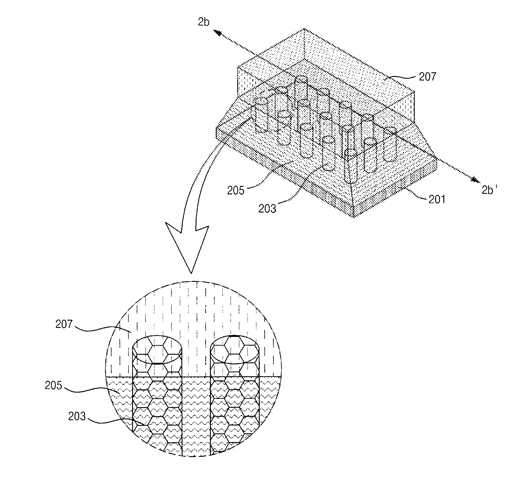
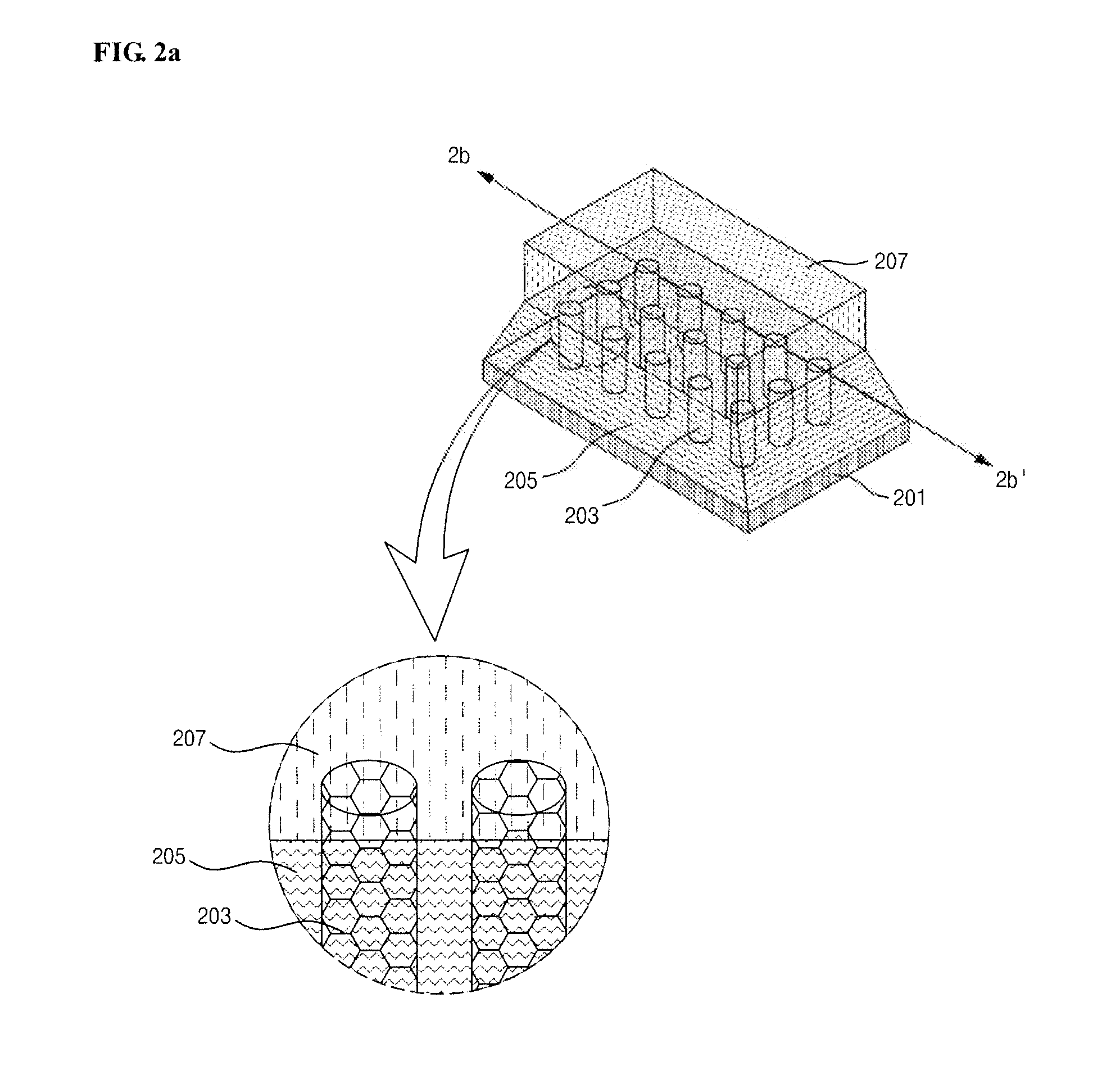
[0058]FIG. 2a is a perspective view of a phase change memory device structure according to an embodiment of the present invention. FIG. 2b is a sectional view of the phase change memory device structure cut in a 2b-2b′ direction illustrated in FIG. 2a. FIG. 2c is a top view of a bottom electrode of the phase change memory device according to the embodiment of the present invention.

[0059]Referring to FIG. 2a, the phase change memory device comprises a current source electrode 201, a phase change material layer 207, a plurality of carbon nanotube electrodes 203, and an insulation layer 205. The current source electrode 201 supplies external current to a target. The phase change material layer 207 is disposed to face the current source electrode 201 in side direction. The carbon nanotu...


PUM

PropertyMeasurementUnit
diameteraaaaaaaaaa
sizeaaaaaaaaaa
external currentaaaaaaaaaa

Abstract

Provided are a phase change memory device that can operate at low power and improve the scale of integration by reducing a contact area between a phase change material and a bottom electrode, and a method for fabricating the same. The phase change memory comprises a current source electrode, a phase change material layer, a plurality of carbon nanotube electrodes, and an insulation layer. The current source electrode supplies external current to a target. The phase change material layer is disposed to face the current source electrode in side direction. The carbon nanotube electrodes are disposed between the current source electrode and the phase change material layer. The insulation layer is formed outside the carbon nanotube electrodes and functions to reduce the loss of heat generated at the carbon nanotube electrodes.

Description

[0001]This nonprovisional application claims priority under 35 U.S.C. § 119(a) on Patent Application No. 10-20060001336 filed in Republic of Korea on Jan. 5, 2006, the entire contents of which are hereby incorporated by reference.BACKGROUND[0002]1. Field[0003]The present invention relates to a phase change memory device, and more particularly, to a phase change memory device using a carbon nanotube to allow operation at low power and large scale of integration, and a method for fabricating the same.[0004]2. Description of the Background Art[0005]A phase change memory device is a type of memory that stores information using an electrical conductivity difference between a crystalline phase and an amorphous phase of a specific material.[0006]Such a phase change memory device has received a great attention as a next generation non-volatile memory due to its unique characteristics such as large threshold voltage margin, rapid operation speed, excellent durability, and long data retention...

Claims


Application Information

Patent Timeline
Patent Type & Authority Applications(United States)
IPC IPC(8): H01L29/768
CPCB82Y10/00G11C13/0004G11C13/025H01L45/16H01L45/1233H01L45/126H01L45/06Y10S977/742Y10S977/752Y10S977/70Y10S977/75H10N70/231H10N70/8413H10N70/826H10N70/011H10N70/061
Inventor CHOI, YANG-KYUKIM, KUK-HWAN
Owner KOREA ADVANCED INST OF SCI & TECH
Why Eureka
Try Eureka