
Boundary acoustic wave device

a acoustic wave and device technology, applied in piezoelectric/electrostrictive/magnetostrictive devices, piezoelectric/electrostriction/magnetostriction machines, electrical apparatus, etc., can solve the problems of increasing loss, and achieve the effect of easy formation and easy formation

Active Publication Date: 2007-07-12
MURATA MFG CO LTD
View PDF6 Cites 20 Cited by
  • Summary
  • Abstract
  • Description
  • Claims
  • Application Information

AI Technical Summary

Benefits of technology

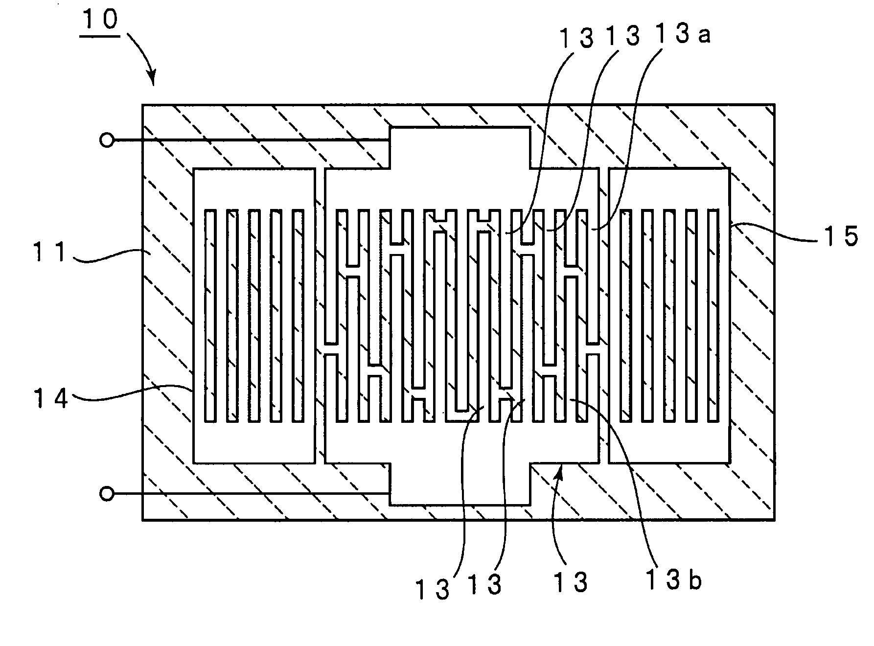
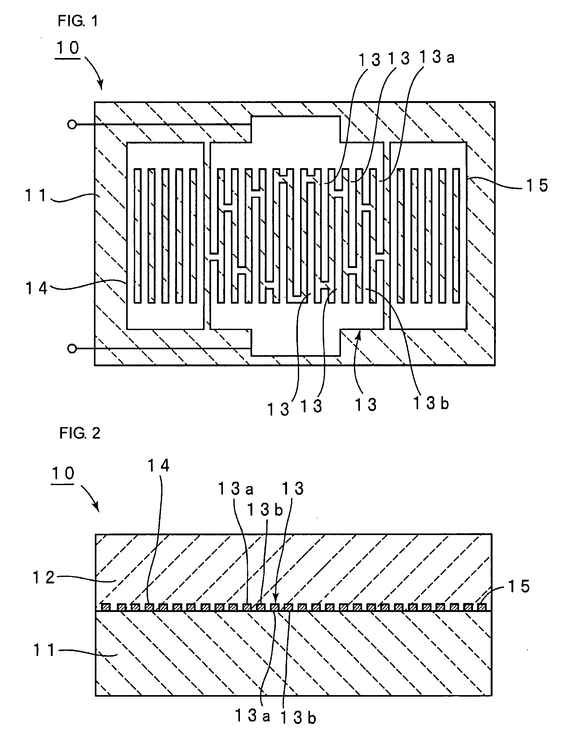
[0009] It is an object of the present invention to solve the shortcomings of the related art and to provide a boundary acoustic wave device in which boundary acoustic waves can be effectively confined even when the operating frequency is increased, and a high electromechanical coupling coefficient can be obtained, and thus which has a low loss.
[0025] In the present invention, when a reflector that is composed of the same electrode materials as the IDT and that is disposed between the first medium and the second medium is further provided, for example, a boundary acoustic wave resonator and a boundary acoustic wave resonator filter that include the reflector can be easily formed in accordance with the present invention.

Problems solved by technology

Consequently, the conductor resistance of the electrode fingers is increased, thereby increasing the loss.

Method used


Image

  • Boundary acoustic wave device
  • Boundary acoustic wave device
  • Boundary acoustic wave device

Examples


Embodiment Construction

[0046] The densities, the Euler angles of crystals, and the crystal axes of materials used as a medium or an electrode material in this description are as follows.

[0047] Density

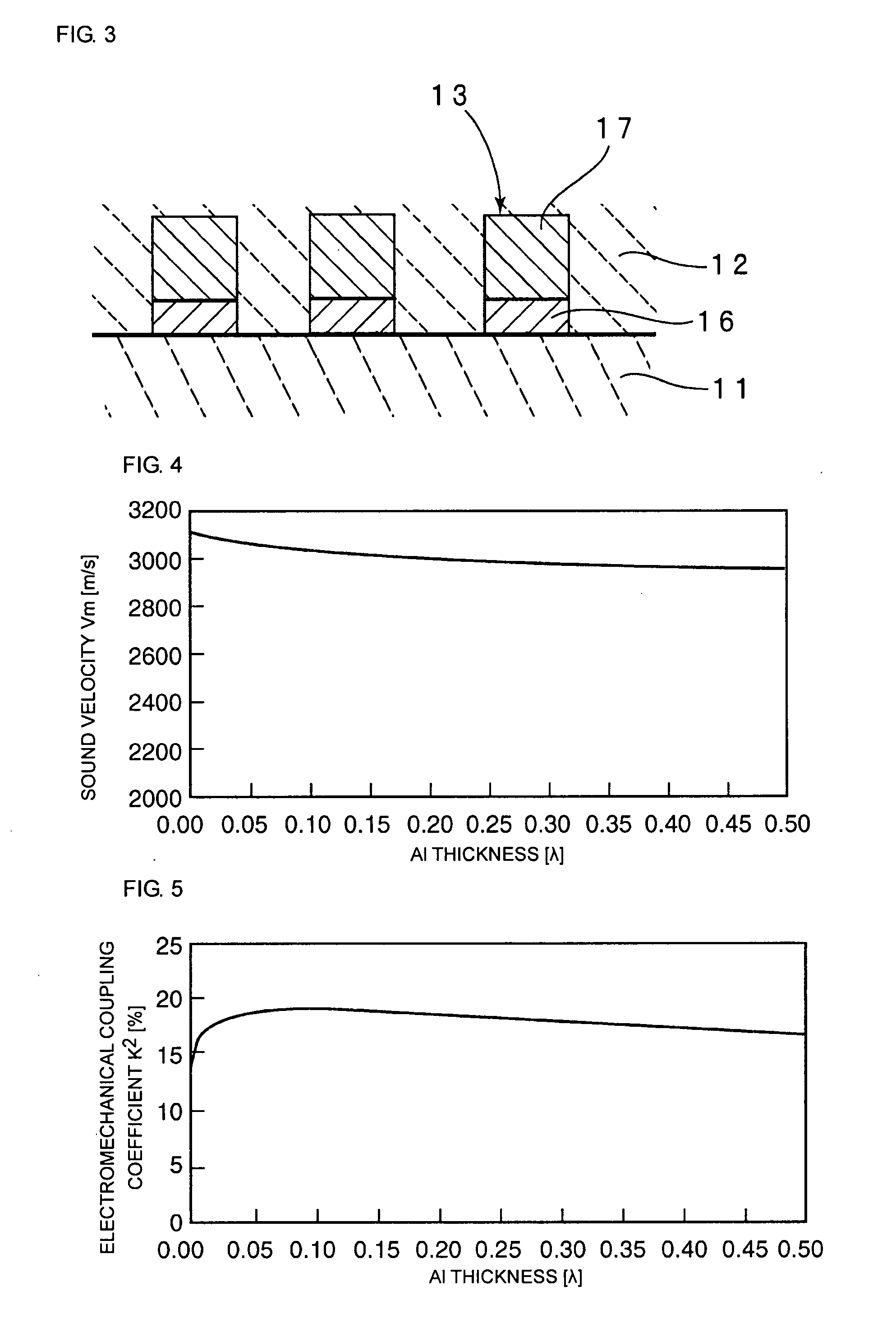
[0048] Silicon dioxide (SiO2) has a density of 2,210 kg / m3 and an acoustic characteristic impedance of transverse waves of 8.3×10⁶ kg·s / m2. Aluminum (Al) has a density of 2,699 kg / m3 and an acoustic characteristic impedance of transverse waves of 8.4×10⁶ kg·s / m2. Copper (Cu) has a density of 8,939 kg / m3 and an acoustic characteristic impedance of transverse waves of 21.4×10⁶ kg·s / m2. Silver (Ag) has a density of 10,500 kg / m3 and an acoustic characteristic impedance of transverse waves of 18.6×10⁶ kg·s / m2. Gold (Au) has a density of 19,300 kg / m3 and an acoustic characteristic impedance of transverse waves of 24.0×10⁶ kg·s / m2.

[0049] Euler Angles

[0050] In this description, the right-handed system Euler angle described in a document of “Danseiha Soshi Gijutsu Handobukku (Acoustic Wave Devices Technical Handbo...


PUM


Abstract

A boundary acoustic wave device is provided in which an increase in the conductor resistance can be suppressed and a satisfactorily high electromechanical coupling coefficient K2 can be achieved even when the frequency is increased. The boundary acoustic wave device includes a first medium, a second medium, and an IDT provided therebetween. In the boundary acoustic wave device, a plane that separates the IDT into two equal parts in the thickness direction is defined as a boundary plane, the energy of boundary acoustic waves that is present at the first medium side of the boundary plane is represented by E1, and the energy that is present at the second medium side of the boundary plane is represented by E2. Furthermore, under the condition that an IDT including only the conductive layer having the highest density among the plurality of conductive layers constituting the IDT is configured so that the sound velocity of boundary acoustic waves when the IDT includes the plurality of conductive layers is equal to the sound velocity of boundary acoustic waves when the IDT includes only the conductive layer having the highest density, the energy of boundary acoustic waves that is present at the first medium side of the boundary plane is represented by E1′ and the energy that is present at the second medium side of the boundary plane is represented by E2′. In this case, the relationship E1 / E2>E1′ / E2′ is satisfied.

Description

CROSS REFERENCE TO RELATED APPLICATIONS [0001] The present application is a continuation of International Application No. PCT / JP2006 / 305503, filed Mar. 20, 2006, which claims priority to Japanese Patent Application No. JP2005-154250, filed, May 26, 2005, the entire contents of each of these applications being incorporated herein by reference in their entirety.FIELD OF THE INVENTION [0002] The present invention relates to a boundary acoustic wave device used as, for example, a resonator or a bandpass filter. More specifically, the present invention relates to a boundary acoustic wave device in which an interdigital transducer (IDT) is disposed between a first medium and a second medium that are composed of different materials. BACKGROUND OF THE INVENTION [0003] A boundary acoustic wave device has a structure in which an interdigital transducer (IDT) is disposed at the interface between different media. In such a boundary acoustic wave device, boundary acoustic waves propagate in a la...

Claims


Application Information

Patent Timeline
IPC IPC(8): H03H9/25
CPCH03H9/0222H03H9/02834H03H9/14541H03H9/14532H03H9/02944
Inventor KANDO, HAJIME
Owner MURATA MFG CO LTD
Learn More