
Angle-tunable transmissive grating

a transmissive grating, angle-tunable technology, applied in the direction of optical radiation measurement, instruments, spectrometry/spectrophotometry/monochromators, etc., can solve the problem that the transmission grating cannot be tuned in the same way, the use of transmissive gratings to fixed-wavelength applications in many optical systems is limited, and the transmission grating such as shown in fig. 1 cannot be efficiently tuned, etc. problem, to achieve the effect of power handling capacity increas

Inactive Publication Date: 2007-07-12
MASSACHUSETTS INST OF TECH
View PDF45 Cites 100 Cited by
  • Summary
  • Abstract
  • Description
  • Claims
  • Application Information

AI Technical Summary

Benefits of technology

[0008]The invention relates to the use of a transmissive dispersive element for tunable-wavelength applications. By taking advantage of the transmissive nature of the transmissive dispersing element such as a grating, many optical designs can be simplified and improved. The invention provides improved optical efficiency, broad bandwidth, thermal stability, lower polarization dependence, spectral purity at a lower cost.
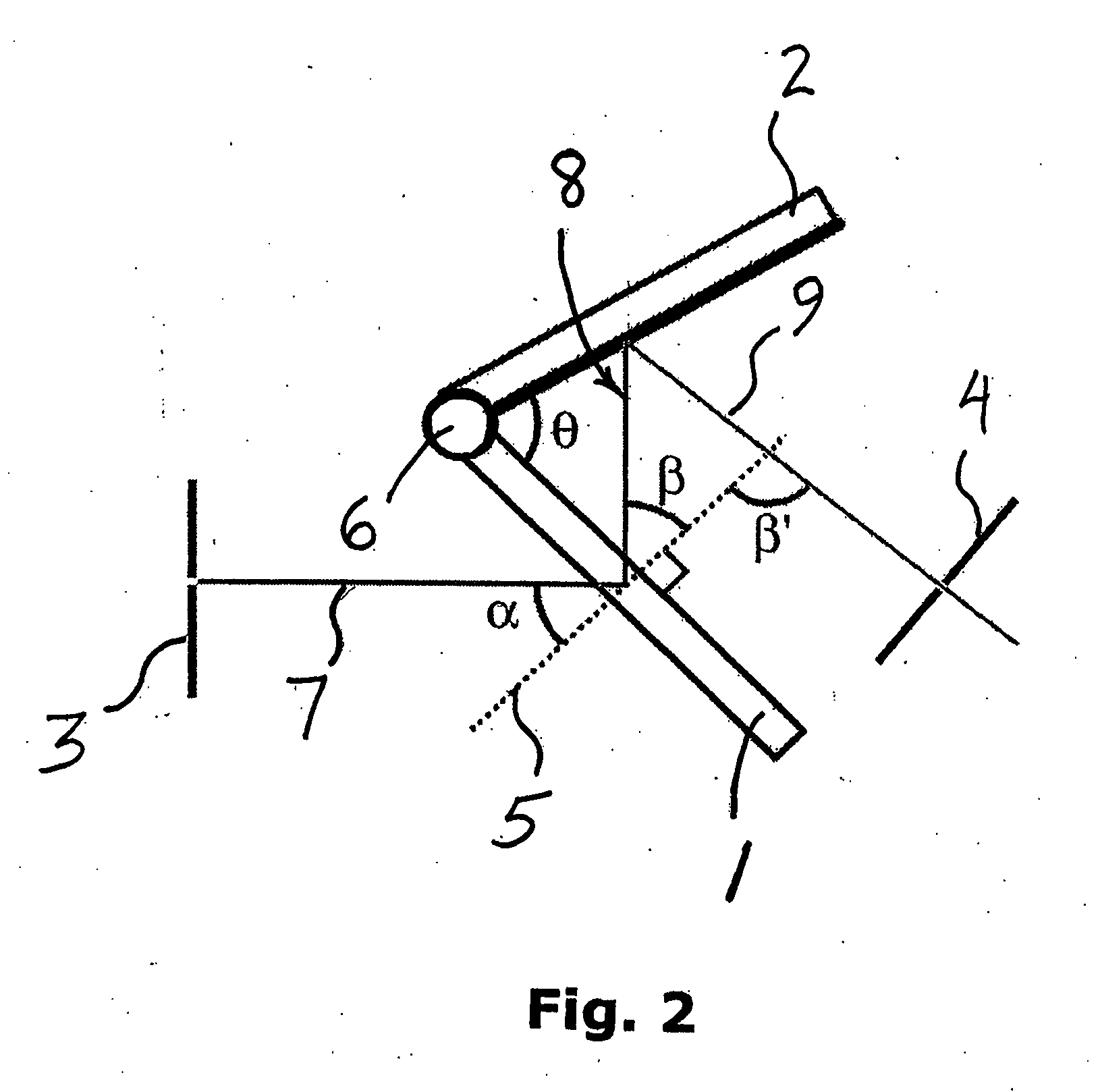
[0009]A preferred embodiment of the invention provides for an optical apparatus for tuning wavelengths of light through a transmissive dispersive element. The apparatus includes a transmissive dispersive element, a reflector, a relative angular position, θ, formed between the dispersive element and the reflector, an optical path comprising an input beam, a diffracted beam and a reflected diffracted beam. In a preferred embodiment, the transmissive dispersive element can be a transmissive grating that diffracts the input beam and the reflector can be a rotatable mirror. Light passing from the transmissive grating is directed onto the mirror according to the relative angular position, θ. Rotating the mirror and / or the grating relative to the input beam efficiently tunes the wavelength of the reflected diffracted beam.
[0015]The invention provides further for using such methods to tune transmissive gratings in existing optical systems, thereby achieving better performance in these optical systems with minimal cost and effort. For example, the invention can provide for retrofitting traditional instruments with the tunable transmissive gratings. Thus, many optical instruments such as spectrometers can have a tunable element described herein installed to provide a compact wavelength tunable system.

Problems solved by technology

Owing to their transmissive nature, however, transmissive gratings cannot be tuned the same way that reflective gratings are tuned, and this has limited the use of transmissive gratings to fixed-wavelength applications in many optical systems.
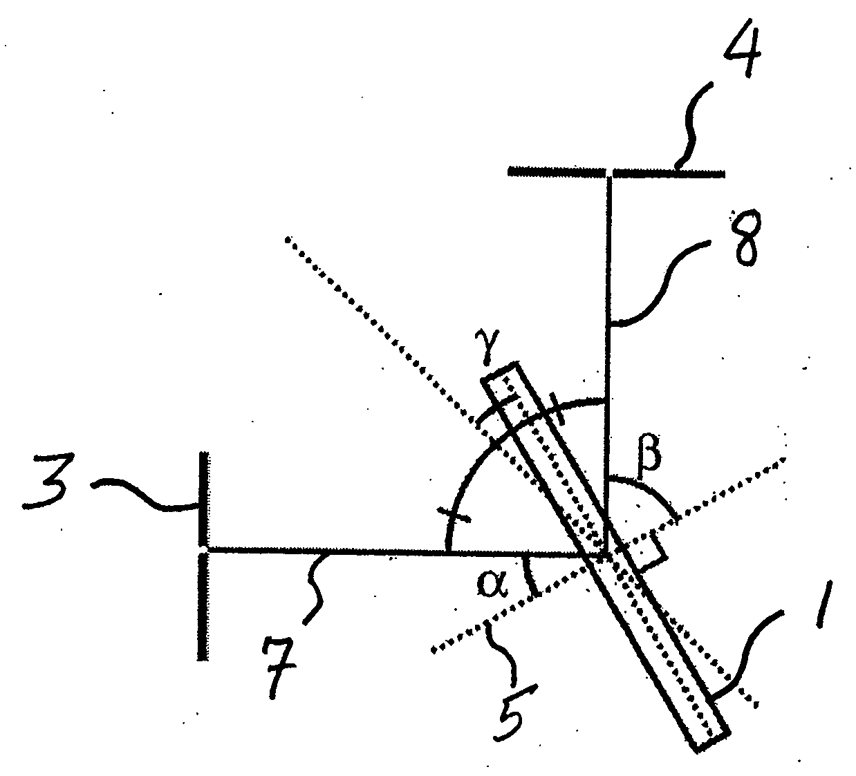
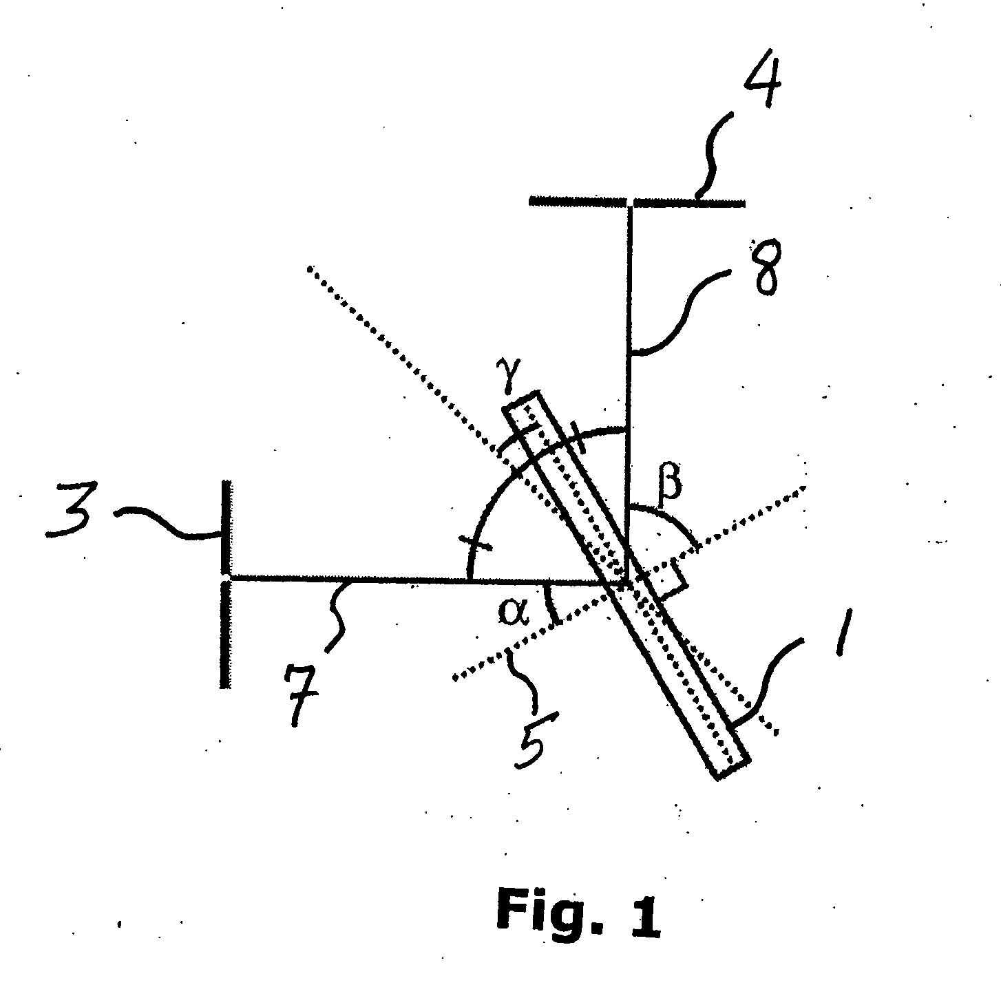
This implies that a transmissive grating such as shown in FIG. 1 cannot be tuned efficiently.

Method used


Image

  • Angle-tunable transmissive grating
  • Angle-tunable transmissive grating
  • Angle-tunable transmissive grating

Examples


Embodiment Construction

[0028]The invention relates to the use transmissive dispersive elements for tunable-wavelength applications. By taking advantage of the transmissive nature of the transmissive dispersing elements such as gratings, many optical designs can be simplified and improved.

[0029]In general, multiple embodiments of the invention provide for an angle-tunable assembly comprising a transmissive dispersive element and a reflective element, wherein at least one element is rotatable about a rotational center to tune the wavelength of a beam of light following an optical path through the transmissive dispersive element and onto the reflective element. Both elements can be rotatable together around a common rotational according to certain embodiments, and / or each element can be independently rotated around a rotational axis associated only with that element. Planar axes of orientation associated with each element can intersect at a line of intersection, which line can coincide with a rotational axis...


PUM


Abstract

A tunable transmissive grating comprises a transmissive dispersive element, a reflective element, and an angle θ formed between the two elements. A first optical path is formed according to the angle θ, wherein light dispersing from the dispersive element is directed onto the reflective element and reflects therefrom. At least one element is rotatable about a rotational center to cause a second optical path and thereby tune the wavelength of the light reflecting from the reflective element. Both elements can be rotatable together around a common rotational center point according to certain embodiments, and / or each element can be independently rotated around a rotational axis associated only with that element. According to some embodiments, the relative angle θ formed between the elements is held constant; however, in other embodiments θ can vary.

Description

CROSS REFERENCE TO RELATED APPLICATIONS[0001]This application claims the priority of U.S. Provisional Application No. 60 / 758,044 filed Jan. 11, 2006 entitled, ANGLE-TUNABLE TRANSMISSIVE GRATING. The entire content of the above application is being incorporated herein by reference.BACKGROUND OF THE INVENTION[0002]New types of transmissive gratings are available with higher efficiency than reflective gratings. Traditionally, reflective gratings have been preferred over transmissive gratings for various optical instruments as their dispersive elements. Reflective gratings have been a key component of various optical instruments such as monochrometers, tunable laser cavities, and beam stretcher / compressors. Not only can reflective gratings be easily tuned, until recently they also promised higher diffraction efficiencies than transmissive gratings.[0003]Transmissive gratings developed recently, however, such as Volume Holographic Transmission (VHT) gratings and Fused Silica (FS) grating...

Claims


Application Information

Patent Timeline
Patent Type & Authority Applications(United States)
IPC IPC(8): G02B6/34H01S3/08
CPCG01J3/02G01J3/021G01J3/06G01J3/1804G01J3/22H01S5/141G02B5/1866G02B6/34G02B27/4244H01S3/1055H01S3/213G02B5/1828
Inventor SON, HYUNGBINKONG, JINGDASARI, RAMACHANDRADRESSELHAUS, MILDRED
Owner MASSACHUSETTS INST OF TECH
Learn More