Automatic gaslight igniter/controller and burners

a technology of automatic gaslight ignition and controller, which is applied in the direction of mechanical igniter, incandescent mantles, lighting and heating apparatus, etc., can solve the problems of difficult to work on a hard-mounted gaslight/burner with distributed components, and it is not practical to send a trained maintenance technician out to the gaslight location to repair the unit, etc., to achieve flexible and reliable, small size, and low cost

Inactive Publication Date: 2007-07-12
KNIGHT ARNOLD W +1
View PDF29 Cites 15 Cited by
  • Summary
  • Abstract
  • Description
  • Claims
  • Application Information

AI Technical Summary

Benefits of technology

[0022] Accordingly it is the primary objective of the present invention to provide a small, low cost, flexible a

Problems solved by technology

It is not practical to send a trained maintenance technician out to the gaslight location to repair the unit.
Even if a trained technician did go to the gaslight si

Method used


Image

  • Automatic gaslight igniter/controller and burners
  • Automatic gaslight igniter/controller and burners
  • Automatic gaslight igniter/controller and burners

Examples


Embodiment Construction

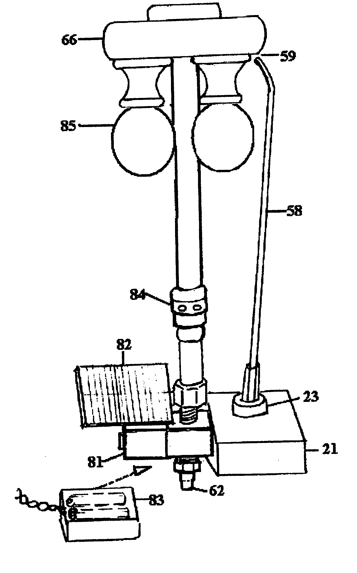
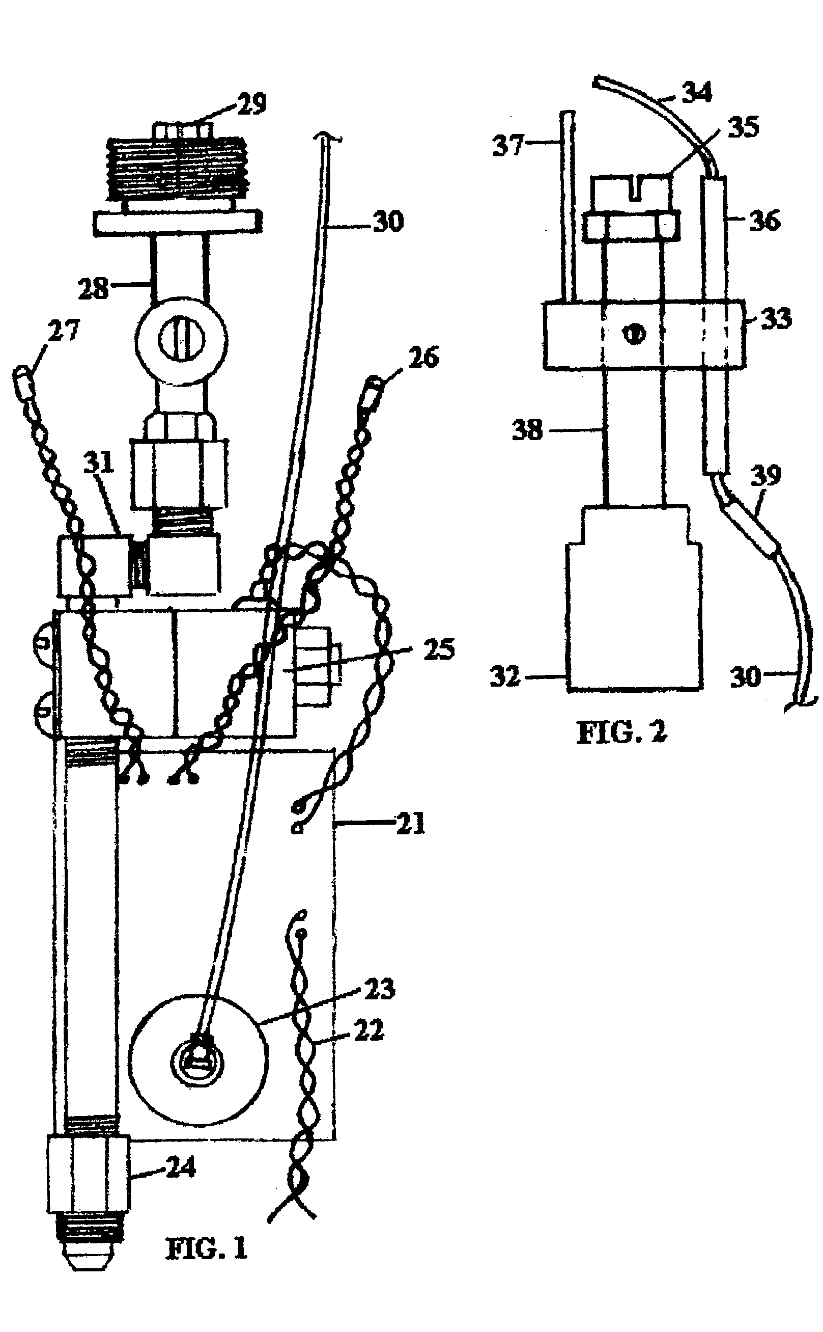
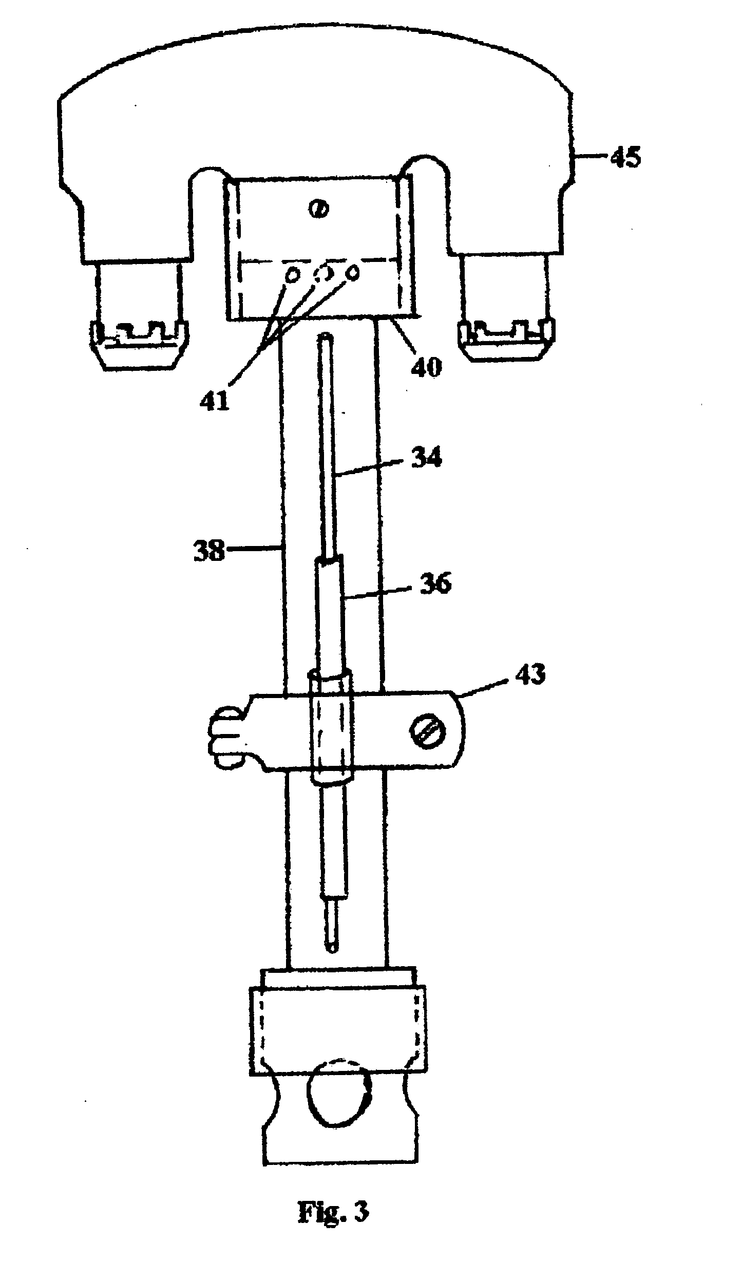
[0115] The baseline automatic igniter / burner configuration is shown in FIGS. 1, 2 and 3. These figures show a post-mounted igniter installed in the top of a 3-inch diameter lamp post, using a Gas Light Manufacturing model GLV-100 manual shutoff valve 28 to hold the igniter to the gas-lamp head. This is the same valve used with many manual gaslights.

[0116] The igniter 21 shown in FIG. 1 operates either with the open flame burner shown in FIG. 2 or the mantle burner shown in FIG. 3.

[0117] The igniter / microcontroller board is potted in an aluminum potting box 51 to form the igniter 21. Low voltage 24 VAC power is connected to the power leads 22. Natural gas, propane or other fuel line is connected to the male flare fitting 24. A solenoid valve 25 is controlled by the microcontroller. A daylight photo-sensor 26 senses ambient daylight and signals the microcontroller to ignite the gaslight at dusk and turn it off at dawn. The flame photo-sensor 27 monitors the burner flame and signals ...


PUM


Abstract

A method and apparatus is defined for automatically igniting and controlling a gaslight to turn ON the gaslight in the evening and turn OFF the gaslight in the morning or alternatively, using a switch or timer to turn the gaslight on and off. The gaslight may be either a mantle type burner or an open flame type burner. The igniter consists of a high voltage spark generator that is controlled by a microcontroller to enable the spark when the microcontroller senses that darkness has occurred or a preset time of day has occurred. The spark is generated across a spark probe gap that is positioned in an optimum location to ignite the gas/air mixture. We and others have been manufacturing gaslight igniters for several years and this patent pertains to recent concepts and implementations that greatly improve the automatic igniter/burner utility and operation.
The physical parameters of the device are also important. The device is sized so that it will fit easily inside of a 3-inch lamppost, or install easily within most gas lamp heads. The device is flexible in configuration to allow the burner/probe to be oriented axially with the igniter, or oriented perpendicular to the igniter to provide great flexibility in using the igniter with various burners and gas light heads. Quick disconnect fittings for gas and low voltage electric make the igniter/burner assembly easy to change without tools, similar to changing a light bulb.

Description

CROSS REFERENCE TO RELATED APPLICATIONS [0001] This application claims the benefit of PPA Ser. No. 60 / 754,475 filed 2005 Dec. 28 by the present inventors.FEDERALLY SPONSORED RESEARCH [0002] Not applicable SEQUENCE LISTING OR PROGRAM [0003] Not applicable BACKGROUND OF INVENTION [0004] 1. Field of Invention [0005] This invention pertains to automatic gaslight igniters / controllers and burners for use with indoor or outdoor automatic gaslights, including natural gas, propane and other fuels. Both open flame and mantle type burners are used and the igniter works with most existing gaslights manufactured or in operation today. The small size and flexibility of the physical unit, which can be configured in several ways to meet specific installation requirements, allows its use with most gas lights. Compressing the igniter, solenoid valve, burner and probe into an integrated unit that is as easy to change as a light bulb is an important feature of this invention. Direct wire probes and sid...

Claims


Application Information

Patent Timeline
IPC IPC(8): F23Q1/04F23Q3/00F21H1/00F23Q9/00F23Q7/12F21L19/00
CPCF23Q3/006F23Q21/00F23Q9/06
Inventor KNIGHT, ARNOLD W.KNIGHT, ANDREW W.
Owner KNIGHT ARNOLD W
Why Eureka
Try Eureka