Re-transmission control method and communication device

a control method and communication device technology, applied in the direction of coding, code conversion, high-level techniques, etc., can solve the problems of unavoidable package error, unclear whether the selected parity is optimal, and the original performance of turbo codes cannot be achieved

Inactive Publication Date: 2007-07-12
MITSUBISHI ELECTRIC CORP
View PDF12 Cites 33 Cited by
  • Summary
  • Abstract
  • Description
  • Claims
  • Application Information

AI Technical Summary

Benefits of technology

[0008] A re-transmission control method for transmitting a codeword encoded at a predetermined coding rate during an initial transmission, and for transmitting an additional parity during a re-transmission, the method comprising: a parity-check matrix generation step of causing a transmitter-side communication device that has received a NAK from a receiver-side communication device to generate a parity-check matrix for the re-transmission so as to include, as a part of the parity-check matrix for the re-transmission, a check matrix (configured by a check symbol generator matrix P and a unit matrix) in an irreducible standard form obtained by transforming a parity-check matrix for the initial transmission; a check matrix transforming step of transforming the parity-check matrix for the re-transmission into a check matrix (configured by a check symbol generator matrix (P+P′) and the unit matrix) in the irreducible standard form; a generator matrix generation step of generating a generator matrix in the irreducible standard form for the re-transmission, which matrix includes the check symbol generator matrix (P+P′);
[0009] an additional parity generation and transmission step of generating the additional parity (=P′×m) using the generator matrix P′ and a message m having a fixed length, performing a predetermined digital modulation on the generated additional parity, and transmitting a modulated signal; and a decoding step of causing the receiver-side communication device to perform a predetermined digital demodulation on the rece...

Problems solved by technology

Particularly in a system intended to improve throughput by selecting an optimum modulation scheme and an optimum coding scheme according to a state of a propagation path (adaptive modulation-demodulation and error correction), packet error is unavoidable.
In addition, with this r...

Method used


Image

  • Re-transmission control method and communication device
  • Re-transmission control method and communication device
  • Re-transmission control method and communication device

Examples


Embodiment Construction

[0024] The present invention will be explained below in detail with reference to the accompanying drawings.

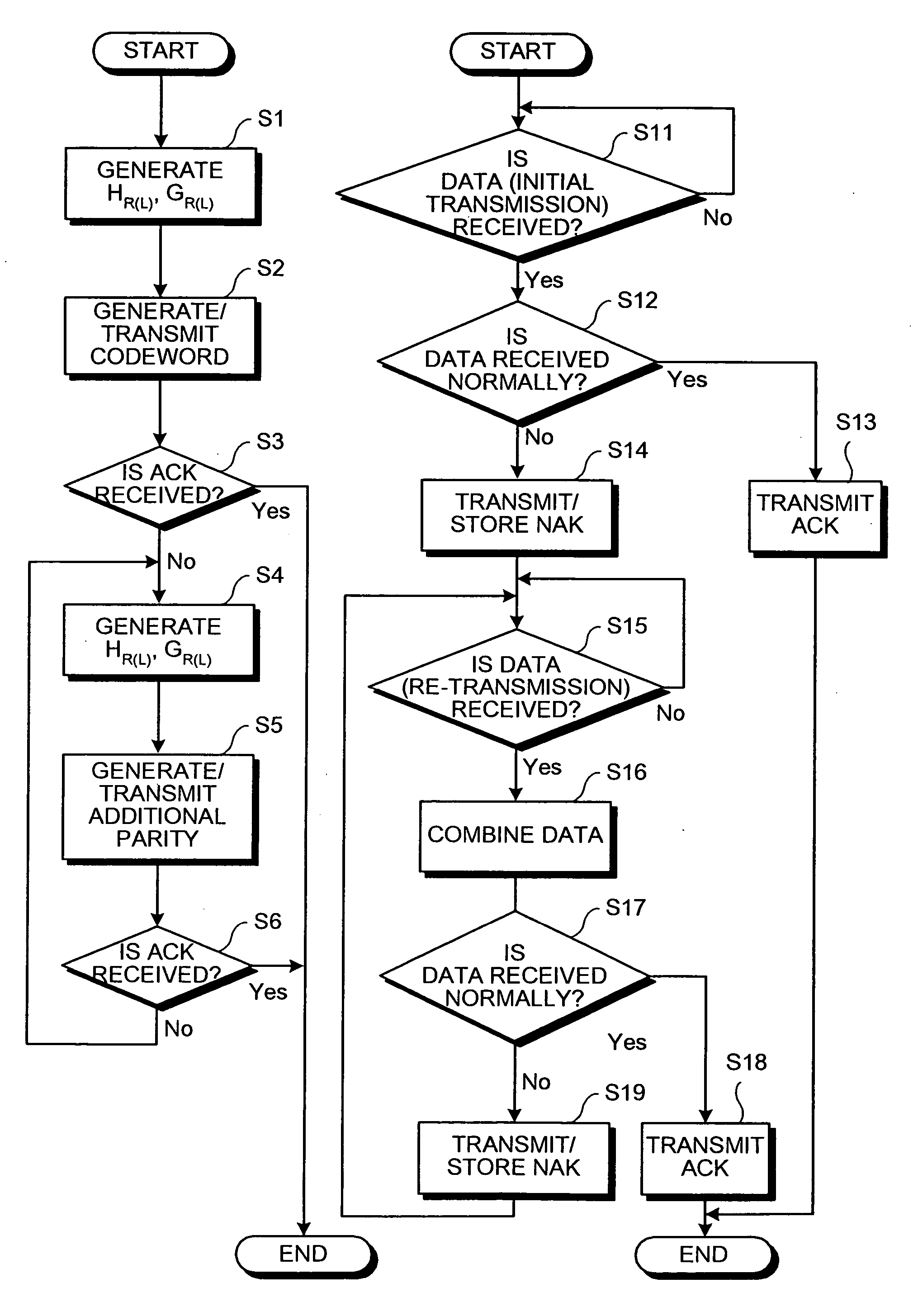
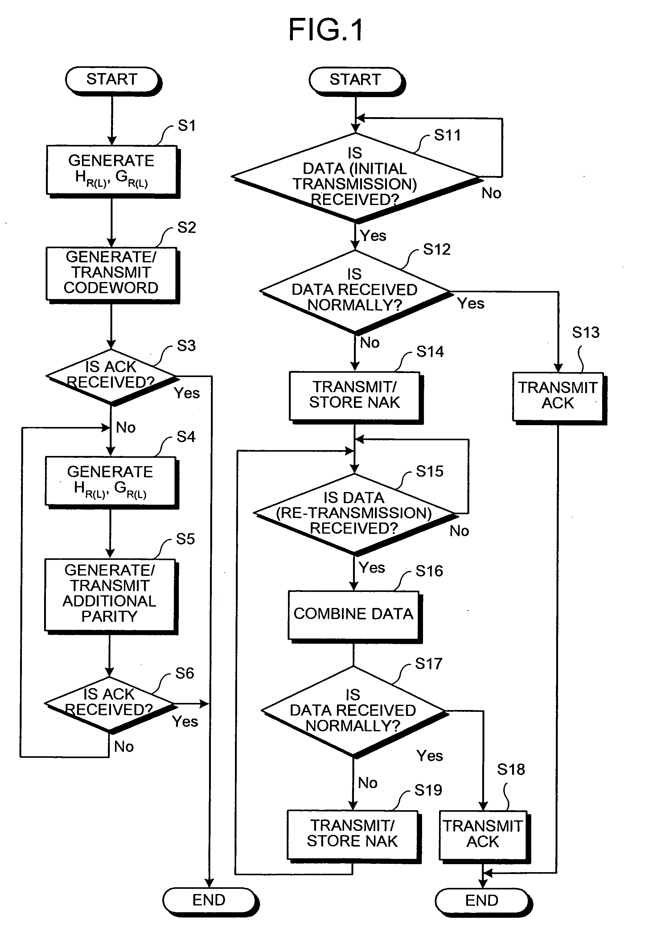
[0025]FIG. 1 is a flowchart of a re-transmission control method according to the present invention. The re-transmission control method using, for example, LDPC codes having characteristics quite close to the Shannon limit as error correcting codes when the Type-II HARQ scheme is adopted, will be explained.

[0026] A parity-check matrix HR(L) for the LDPC codes according to an embodiment of the present invention can be configured to be generated either in a communication device according to set parameters, or by the other control device (for example, a calculator) outside the communication device. When the parity-check matrix HR(L) is generated outside the communication device, the generated parity-check matrix HR(L) is stored in the communication device. In the following embodiment, an instance of generating the parity-check matrix HR(L) in the communication device will be expl...


PUM


Abstract

A re-transmission control method for a transmitting device that transmits a codeword generated based on a first parity-check matrix to a receiving device, and re-transmits a k-th additional parity generated based on a k-th parity-check matrix to the receiving device when receiving a NAK for the codeword or a (k−1)-th additional parity, comprising: generating a (k+1)-th parity-check matrix based on a k-th parity-check matrix; generating a generator matrix based on the (k+1)-th parity-check matrix; and generating the k-th additional parity based on the generator matrix.

Description

TECHNICAL FIELD [0001] The present invention relates to a re-transmission control method that can be realized in systems using low-density parity-check (LDPC) codes as error correcting codes, and to a Communication device constituting-the systems. More specifically, the invention relates to a re-transmission control method and a communication device for an instance of applying LDPC codes to a Type-II HARQ (Hybrid Automatic Repeat reQuest) scheme. BACKGROUND ART [0002] A conventional re-transmission control method will be explained. Examples of error control include error correction coding (FEC: forward error correction) and automatic re-transmission request (ARQ: Automatic Repeat reQuest). Since it is necessary to secure error-free transmission, ARQ-based error correction is essential to packet transmission. Particularly in a system intended to improve throughput by selecting an optimum modulation scheme and an optimum coding scheme according to a state of a propagation path (adapti...

Claims


Application Information

Patent Timeline
IPC IPC(8): H04L1/18H04L1/00
CPCH04L1/0057H04L1/1819H04L1/08H04L1/0002H04L1/0041H04L1/1845Y02D30/50
Inventor MATSUMOTO, WATARU
Owner MITSUBISHI ELECTRIC CORP
Why Eureka
Try Eureka