Signal transmitting method and transmitter in radio multiplex transmission system

a transmission system and signal transmission technology, applied in multiplex communication, code conversion, coding, etc., can solve the problems of high-speed processing imposing a heavy implementation burden, and achieve the effect of reducing processing speed, space diversity effect, and reducing processing speed

Inactive Publication Date: 2007-07-12
NTT DOCOMO INC
View PDF3 Cites 33 Cited by
  • Summary
  • Abstract
  • Description
  • Claims
  • Application Information

AI Technical Summary

Benefits of technology

[0020] (1) On the transmission side, the error-correcting encoding process and the interleaving process are performed for each of the transmission antennas after information is serial-to-parallel converted into the same number of data series as the transmission antennas. On the reception side, the deinterleaving process and the error-correcting decoding process are performed on each of the signal data series after the signal separation. Transmitted information is recovered after the parallel-to-serial conversion. Thus, it is possible to reduce the processing speed required for each error-correcting encoder, error-correcting decoder, and interleaver and / or deinterleaver.
[0021] (2) On the transmission side, the error-correcting encoding process is independently performed for each of the transmission antennas in a parallel manner after information is serial-to-parallel converted into the same number of data series as the transmission antennas. The interleaving process is performed after the parallel-to-serial conversion. On the reception side, the deinterleaving process is performed on each of the separated signal data series after the parallel-to-serial conversion. Further, the error-correcting decoding process is independently performed on each of the signal data series in a parallel manner after the serial-to-parallel conversion. Transmitted information is recovered after the parallel-to-serial conversion. Thus, it is possible to reduce the processing speed required for each error-correcting encoder and error-correcting decoder and to gain a space diversity effect.
[0022] (3) On the transmission side, the error-correcting encoding process is performed before information is serial-to-parallel converted into the same number of data series as the transmission antennas. The interleaving process is performed for each of the transmission antennas after the serial-to-parallel conversion on the reception side, the deinterleaving process is performed on each of the separated signal data series. Further, the error-correcting decoding process is performed after the parallel-to-serial conversion, thereby recovering transmitted information. Thus, it is possible to reduce the amount of processing in each interleaver and deinterleaver.

Problems solved by technology

This high-speed processing imposes a heavy work load in terms of implementation and thus poses a problem.

Method used


Image

  • Signal transmitting method and transmitter in radio multiplex transmission system
  • Signal transmitting method and transmitter in radio multiplex transmission system
  • Signal transmitting method and transmitter in radio multiplex transmission system

Examples


embodiment 1

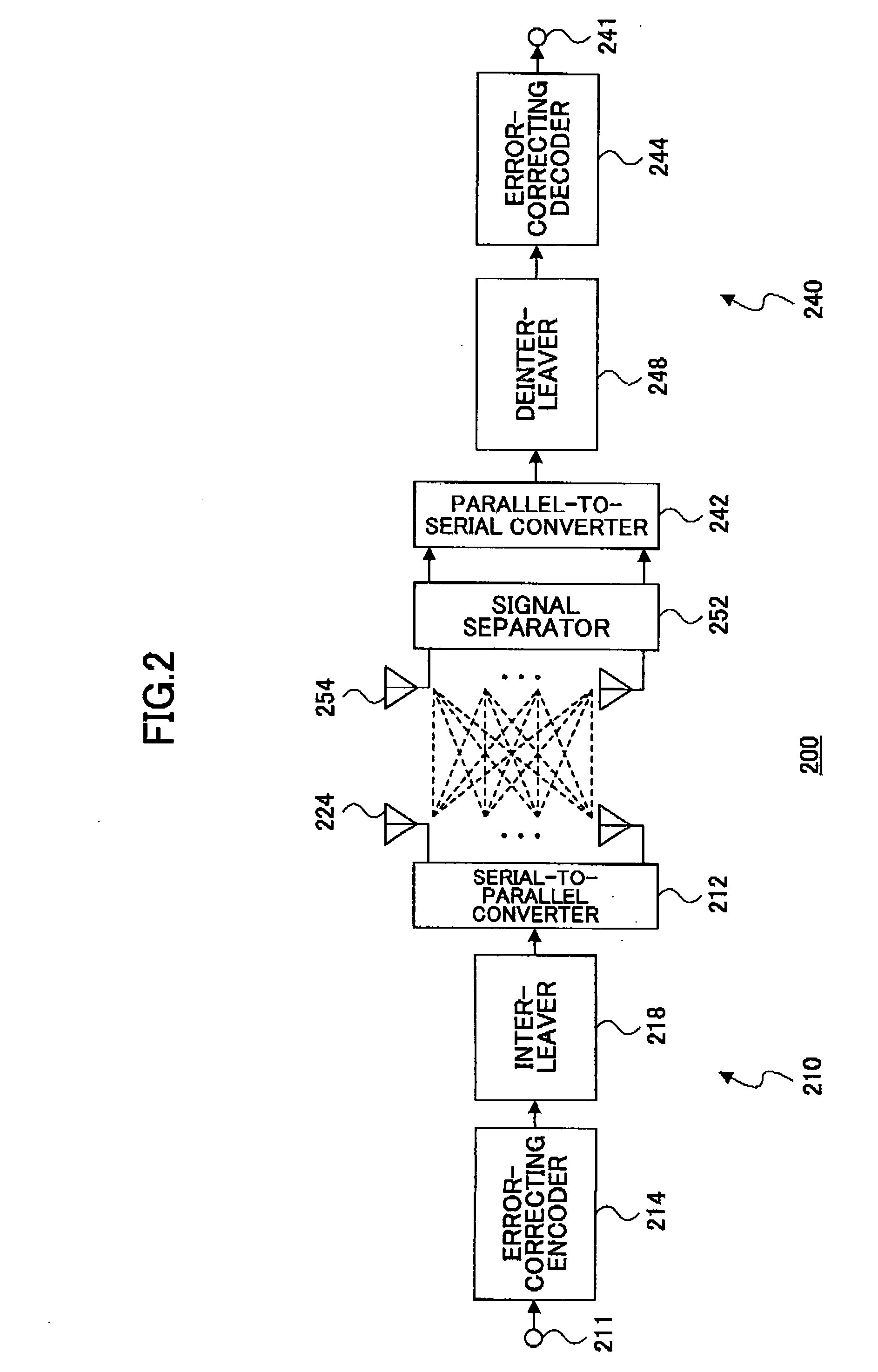
[0033]FIG. 3 is a schematic block diagram of a MIMO transmission system according to a first embodiment of the present invention. A transmitter 310 comprises a serial-to-parallel converter 312, N error-correcting encoders 314, N interleavers 318, and N antennas 324. A receiver 340 comprises N antennas 354, a signal separator 352, N deinterleavers 348, N error-correcting decoders 344, and a parallel-to-serial converter 342.

[0034] In the transmitter 310, first, serial transmission data 311 are serial-to-parallel converted. N parallel data series gained through the serial-to-parallel conversion are encoded with error-correcting codes and interleaved. Thereafter, each parallel data series is transmitted using the corresponding antenna 324.

[0035] Then, each of the antennas 354 of the receiver 340 receives signals transmitted from the transmitter 310. The received signals are separated into N parallel signals using the signal separator 352 of the receiver 340. The N parallel signals aft...

embodiment 2

[0037]FIG. 4 is a schematic block diagram of a MIMO transmission system according to a second embodiment of the present invention. A transmitter 410 comprises a serial-to-parallel converter 412, M error-correcting encoders 414, a parallel-to-serial converter 416, an interleaver 418, a serial-to-parallel converter 420, and N antennas 424. A receiver 440 comprises N antennas 454, a signal separator 452, a parallel-to-serial converter 450, a deinterleaver 448, a serial-to-parallel converter 446, M error-correcting decoders 444, and a parallel-to-serial converter 442.

[0038] In the transmitter 410, first, serial transmission data 411 is serial-to-parallel converted. M parallel data series gained through the serial-to-parallel conversion are encoded with error-correcting codes independently in a parallel manner. Thereafter, the encoded parallel data series are parallel-to-serial converted and interleaved. The interleaved serial data are serial-to-parallel converted, and then each of the ...

embodiment 3

[0043]FIG. 5 is a schematic block diagram of a MIMO transmission system according to a third embodiment of the present invention. A transmitter 510 comprises an error-correcting encoder 514, a serial-to-parallel converter 520, an interleaver 518, and N antennas 524. A receiver 540 comprises N antennas 554, a signal separator 552, a deinterleaver 548, a parallel-to-serial converter 542, and an error-correcting decoder 544.

[0044] In the transmitter 510, first, serial transmission data 511 are encoded with error-correcting codes. Then, the encoded data are serial-to-parallel converted and N parallel data series gained through the serial-to-parallel conversion are interleaved independently in a parallel manner. Thereafter, each parallel data series is transmitted using the corresponding antenna 524.

[0045] Then, each of the N antennas 554 of the receiver 540 receives signals transmitted from the transmitter 510. The received signals are separated into N parallel signals using the signa...


PUM


Abstract

A disclosed signal transmission method in a radio multiplex transmission system comprises the steps of: serial-to-parallel converting serial data to be transmitted into N (N: two or more) parallel data series; independently performing an error-correcting encoding process on the parallel signals of the N data series serial-to-parallel converted; parallel-to-serial converting the parallel signals encoded with error-correcting codes; performing an interleaving process on the parallel-to-serial converted signals; serial-to-parallel converting the interleaved signals into L (L: two or more) parallel data series and transmitting each of the L data series using L antennas; receiving the transmitted signals; separating the received signals into M (M: two or more) data series and parallel-to-serial converting the M data series; performing a deinterleaving process on the parallel-to-serial converted signals; serial-to-parallel converting the deinterleaved signals into N data series; independently performing an error-correcting decoding process on the parallel signals of the N data series serial-to-parallel converted; and parallel-to-serial converting the signals in which the error-correcting codes are decoded, thereby recovering the transmitted data.

Description

TECHNICAL FIELD [0001] The present invention generally relates to a signal transmission method and a transmitter in a radio multiplex transmission system and more particularly to a transmission method and a transmitter in a MIMO transmission system, in which the amount of processing for error-correcting encoding, interleaving, and deinterleaving and / or error-correcting decoding is reduced. BACKGROUND ART [0002] In a radio communication method such as CDMA, for example, it is important to realize a high-speed information rate. One known signal transmission method uses MIMO (Multiple-Input Multiple-Output) channels with plural transmission / reception antennas in order to achieve such a rate. In the MIMO transmission method, both a transmission side and a reception side have N disposed antennas and plural different signals are efficiently transmitted at the same time using the same frequency band through a network with N port inputs and N port outputs connected via a radio circuit. In o...

Claims


Application Information

Patent Timeline
Patent Type & Authority Applications(United States)
IPC IPC(8): H03M13/00H04B7/08H04J99/00
CPCH04B7/0854H04L1/0625H04L1/0071H04L1/0043
Inventor KAWAMOTO, JUNICHIROASAI, TAKAHIROHIGUCHI, KENICHISAWAHASHI, MAMORU
Owner NTT DOCOMO INC
Why Eureka
Try Eureka