System and method for recovering carbon dioxide in exhaust gas

a carbon dioxide and exhaust gas technology, applied in the field of systems for recovering carbon dioxide, can solve the problems of inability to improve thermal efficiency, and the enormous flow rate of alkaline solution 304/b> required in the carbon dioxide absorption step cannot be lowered to a smaller flow rate in the regeneration step

Inactive Publication Date: 2007-07-19
KK TOSHIBA
View PDF5 Cites 55 Cited by
  • Summary
  • Abstract
  • Description
  • Claims
  • Application Information

AI Technical Summary

Benefits of technology

[0014] The present invention provides a system and a method for recovering carbon dioxide contained in an exhaust gas that can regenerate an alkaline solution without using a large volume of steam of a power generation boiler and can circulate the alkaline solution to an absorption device and a regeneration device through individually independent reflux lines.
[0016] According to the system for recovering the carbon dioxide in the exhaust gas, the first alkaline solution reflux line, which refluxes the alkaline solution being discharged from the alkaline solution discharge port of the absorption device to the alkaline solution introduction port and absorbs carbon dioxide, and the second alkaline solution reflux line, which refluxes the regenerated alkaline solution being discharged from the regenerated alkaline solution discharge port of the regeneration device to the alkaline solution spurt port and discharges carbon dioxide to regenerate the alkaline solution can be disposed separately and independently. Thus, the flow rates of the alkaline solutions flowing through the individual alkaline solution reflux lines can be set independently, and a reflux flow rate and the like of the alkaline solution suitable for each of the carbon dioxide absorption operation and the alkaline solution regeneration operation can be set. And, the system for recovering carbon dioxide contained in an exhaust gas does not need to heat instantaneously the alkaline solution by the regeneration device and does not need a large heating device or large heat quantity. Thus, the thermal efficiency of the system can be improved.
[0018] According to the method for recovering carbon dioxide contained in an exhaust gas, the reflux line of the first alkaline solution which absorbs carbon dioxide and the reflux line of the alkaline solution to regenerate the first alkaline solution by discharging the carbon dioxide are separately disposed independently, and the reflux lines can be switched to selectively reflux the first alkaline solution to the individual reflux lines. The flow rates of the first alkaline solutions flowing through the individual reflux lines can be set individually, and a reflux flow rate and the like of the first alkaline solution suitable for a carbon dioxide absorption operation and an alkaline solution regeneration operation can be set. The system for recovering carbon dioxide contained in the exhaust gas does not need to heat instantaneously the alkaline solution by the regeneration device and does not need a large heating device or large heat quantity. Thus, the thermal efficiency of the system can be improved.

Problems solved by technology

In the above-described conventional carbon dioxide recovery system, large heat quantity from the steam 309 of the power generation boiler is used to heat an enormous flow rate of the alkaline solution 304 instantaneously up to a prescribed temperature by the regenerator 307, so that the above system has a problem that the thermal efficiency cannot be improved.
Therefore, the enormous flow rate of the alkaline solution 304 required in the carbon dioxide absorption step cannot be lowered to a smaller flow rate in a regeneration step.

Method used


Image

  • System and method for recovering carbon dioxide in exhaust gas
  • System and method for recovering carbon dioxide in exhaust gas
  • System and method for recovering carbon dioxide in exhaust gas

Examples


first embodiment

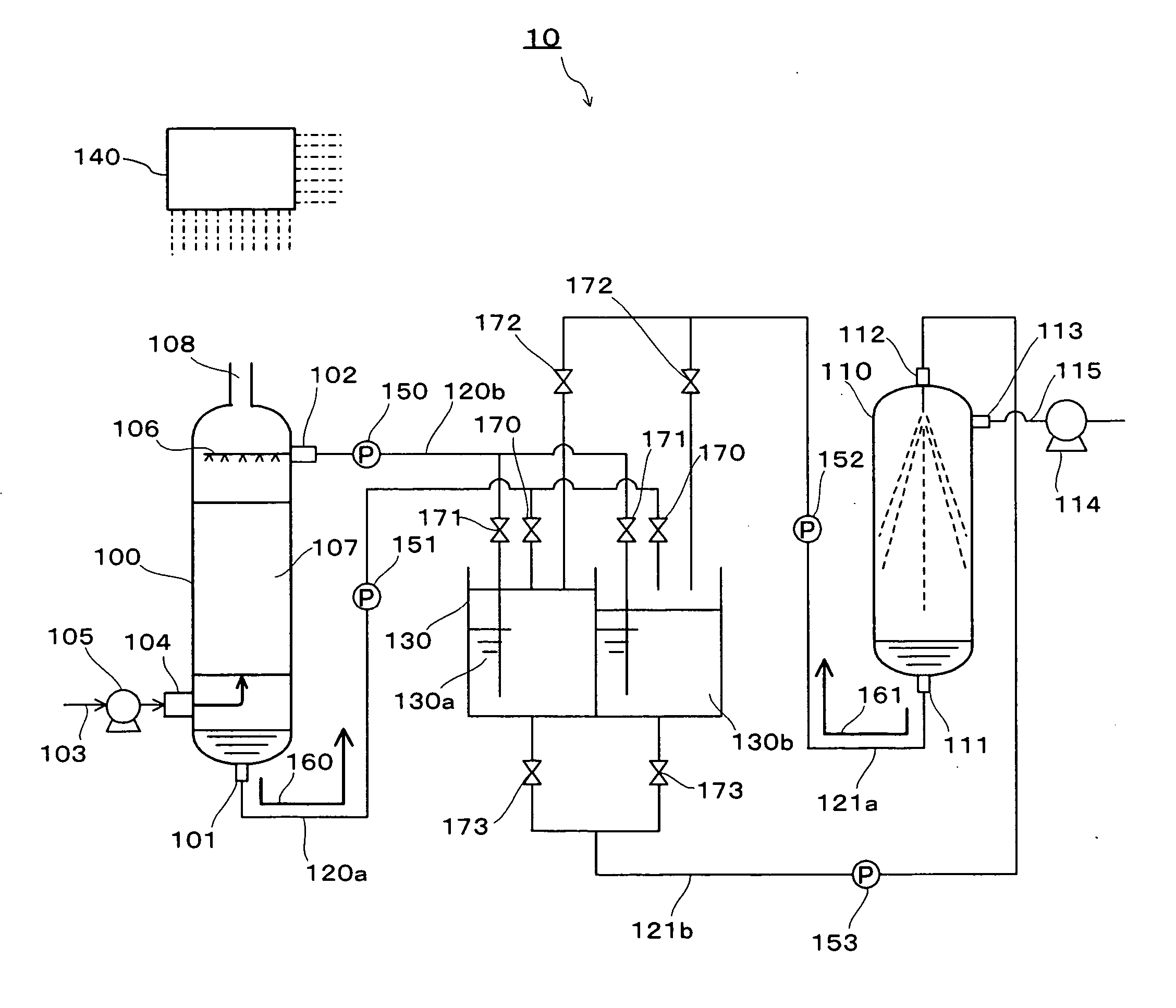
[0032]FIG. 1 shows a general view of a carbon dioxide recovery system 10 of the first embodiment of the present invention.

[0033] The carbon dioxide recovery system 10 is mainly comprised of an absorber 100 in which gas-liquid contact of the introduced exhaust gas and an alkaline solution is performed, a regenerator 110 which generates an alkaline solution by discharging carbon dioxide from the alkaline solution having absorbed the carbon dioxide, alkaline solution reflux lines 120a, 120b which reflux the alkaline solution being discharged from an alkaline solution discharge port 101 of the absorber 100 to an alkaline solution introduction port 102, alkaline solution reflux lines 121a, 121b which reflux the regenerated alkaline solution being discharged from a regenerated alkaline solution discharge port 111 of the regenerator 110 to an alkaline solution jet port 112, a storage tank 130 which is comprised of plural split tanks 130a, 130b intervened in the alkaline solution reflux li...

second embodiment

[0091] The carbon dioxide recovery system according to the second embodiment of the present invention uses a potassium carbonate solution as the alkaline solution of the carbon dioxide recovery system 10 of the above-described first embodiment. Therefore, the basic structure and operation of the carbon dioxide recovery system of the second embodiment are same as those of the carbon dioxide recovery system 10 of the first embodiment, so that the carbon dioxide recovery system of the second embodiment will be described with reference to FIG. 1, and descriptions overlapping those of the carbon dioxide recovery system 10 of the first embodiment will be omitted.

[0092] The alkaline solution used by the carbon dioxide recovery system of the second embodiment is prepared by adjusting a weight concentration to 9 to 30% by dissolving 10 to 43 g of potassium carbonate into 100 g of water. Here, the weight concentration of the potassium carbonate is set to 9 to 30% because if the weight concen...

third embodiment

[0101] The carbon dioxide recovery system according to the third embodiment of the present invention uses an aqueous amine solution as the alkaline solution of the carbon dioxide recovery system 10 of the above-described first embodiment. Therefore, the basic structure and operation of the carbon dioxide recovery system of the third embodiment are same as those of the carbon dioxide recovery system 10 of the first embodiment, so that the carbon dioxide recovery system of the third embodiment will be described with reference to FIG. 1, and descriptions overlapping those of the carbon dioxide recovery system 10 of the first embodiment will be omitted.

[0102] The alkaline solution used by the carbon dioxide recovery system of the third embodiment is prepared by adjusting a weight concentration to 9 to 30% by dissolving 10 to 43 g of amine into 100 g of water. The amine used here includes monoethanolamine (MEA), 2-amino-2-methyl-1-propanol (AMP) and the like.

[0103] Here, the weight con...


PUM

PropertyMeasurementUnit
temperatureaaaaaaaaaa

Abstract

An alkaline solution ref lux path which refluxes an alkaline solution being discharged from an alkaline solution discharge port 101 of an absorber 100 to an alkaline solution introduction port 102 to absorb carbon dioxide and the like, and an alkaline solution reflux path which refluxes a regenerated alkaline solution being discharged from a regenerated alkaline solution discharge port 111 of a regenerator 110 to an alkaline solution jet port 112 and discharges the carbon dioxide to regenerate an alkaline solution are disposed separately and independently. Thus, the flow rates and the like of the alkaline solutions flowing through the individual alkaline solution reflux paths can be set individually.

Description

TECHNICAL FIELD [0001] The present invention relates to a system for recovering carbon dioxide being discharged from a thermal power plant, a municipal waste incineration plant, a natural gas extraction site or the like, and more particularly to a system and method for recovering carbon dioxide in an exhaust gas, which can recover carbon dioxide by an alkaline solution. BACKGROUND ART [0002] In these years, there is an increasing significant concern in connection with a global warming issue caused by a greenhouse effect of carbon dioxide which is a combustion product from the burning of fossil fuels. According to the Kyoto Protocol to the United Nations Framework Convention on Climate Change, Japan is required to reduce the greenhouse gas emission through the years of 2008-2012 to a level 6% below the total emission in 1990.[0003] Under the circumstances as described above, there is disclosed in, for example, JP-A 4-346816 (KOKAI) a system for recovering carbon dioxide by using, for...

Claims


Application Information

Patent Timeline
Patent Type & Authority Applications(United States)
IPC IPC(8): B01D53/62B01D53/14C01B17/16C01B32/50
CPCB01D53/62Y02C10/06Y02C10/04C01B31/20C01B32/50Y02P20/151Y02C20/40
Inventor MORIYAMA, HIDESHIGEMATSUNAGA, KENTAROYAMASHITA, KATSUYA
Owner KK TOSHIBA
Why Eureka
Try Eureka