Hybrid drive system and method of installing same

a hybrid drive and drive system technology, applied in the direction of capacitor propulsion, electric devices, transportation and packaging, etc., can solve the problems of difficult to modify the engine or engine controller to support the newly installed hybrid components, difficult to modify the microprocessor with specialized tools and knowledge, and cost prohibitive or difficult to modify a conventional vehicle to a hybrid vehicle. to achieve the effect of convenient control of the motor

Inactive Publication Date: 2007-07-19
GENERAL ELECTRIC CO
View PDF18 Cites 54 Cited by
  • Summary
  • Abstract
  • Description
  • Claims
  • Application Information

AI Technical Summary

Benefits of technology

[0006]In one aspect, a method of retrofitting a vehicle that includes a heat engine, a transmission coupled to the heat engine, a differential coupled to the transmission, an engine controller coupled to the heat engine, and a plurality of sensors coupled to the engine controller is p

Problems solved by technology

While this method allows the modified engine controller to control both the engine components and the hybrid components, the engine or engine controller is often difficult to modify to support the newly installed hybrid components.
However, modifying the microprocessor requir

Method used


Image

  • Hybrid drive system and method of installing same
  • Hybrid drive system and method of installing same
  • Hybrid drive system and method of installing same

Examples


Embodiment Construction

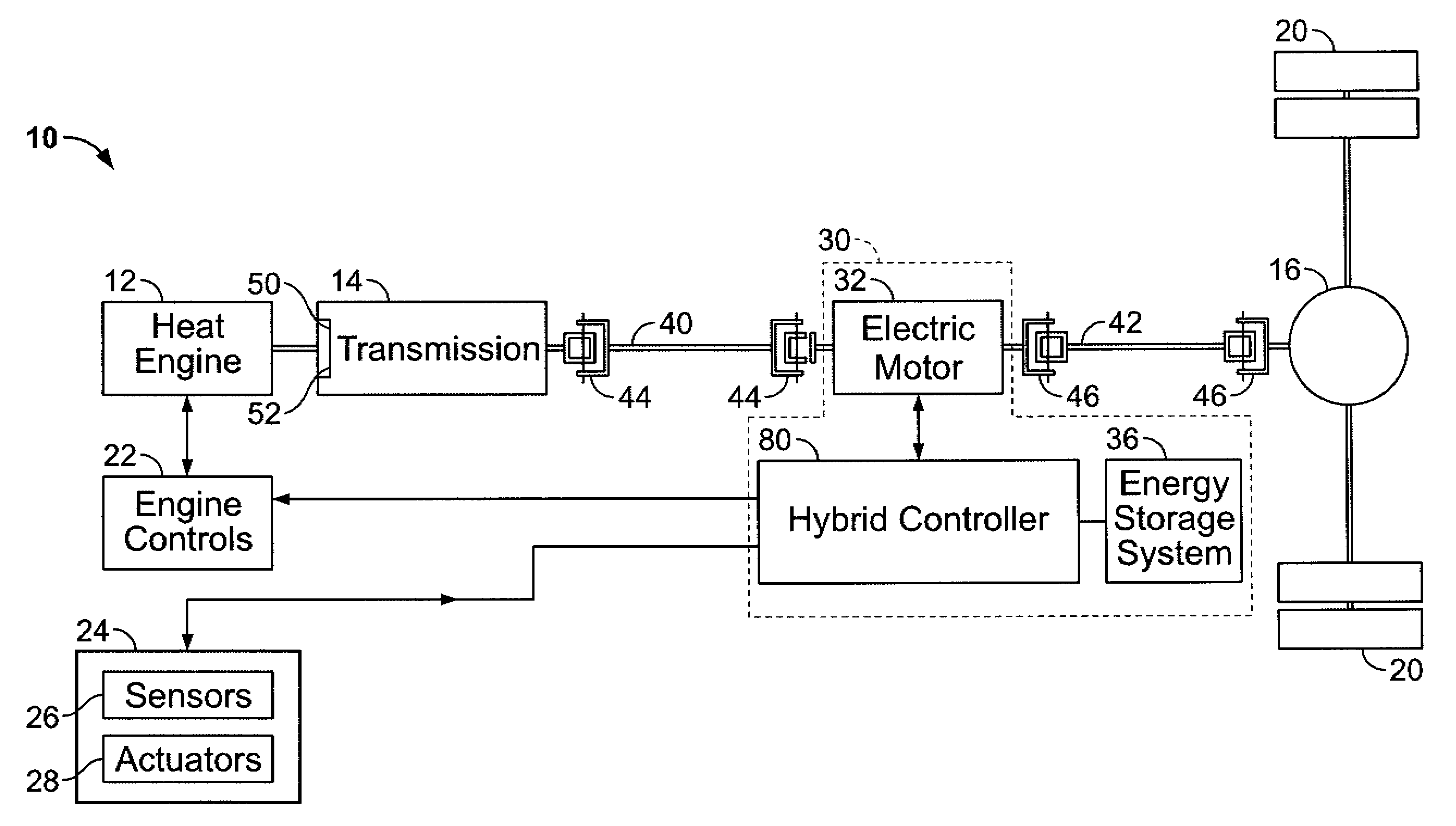
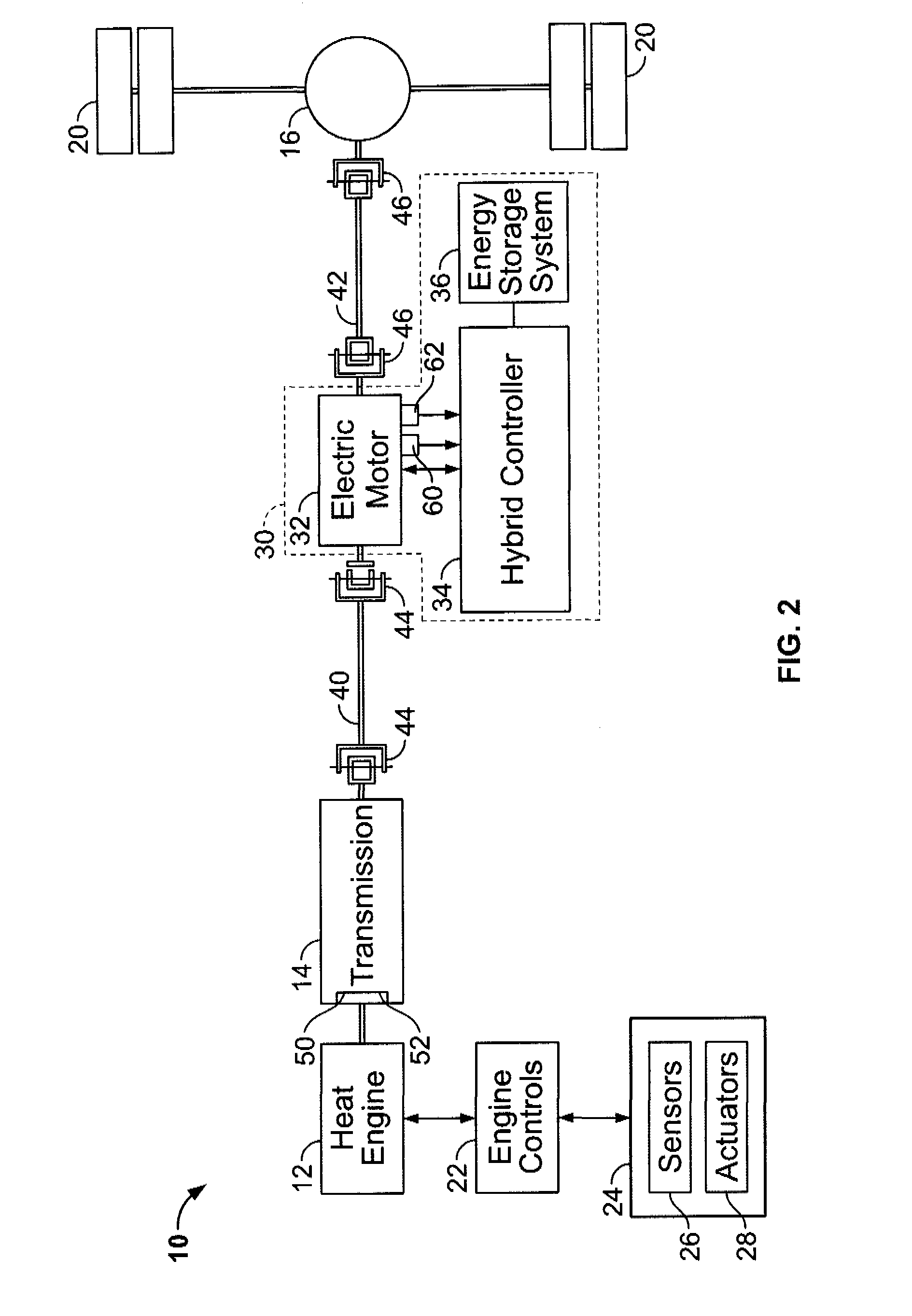
[0016]FIG. 1 illustrates a conventional vehicle 8 that includes a heat engine 12, a transmission 14 that is coupled to the engine 12, a differential 16, and at least one drive shaft 18 that is coupled between the transmission 14 and the differential 16. Vehicle 8 also includes at least two wheels 20 that are coupled to respective ends of the differential 16. In one embodiment, vehicle 8 is configured as a rear wheel drive vehicle such that differential 16 is positioned near the aft end of vehicle 8 and therefore configured to drive at least one of the wheels 20. Optionally, vehicle 8 may be configured as a front wheel drive vehicle. In the exemplary embodiment, heat engine 12 may be implemented using at least one of an internal combustion gasoline engine, an internal combustion diesel engine, an external combustion engine such as a steam engine, or any engine that utilizes natural gas, biofuel, or hydrogen in the combustion process. Moreover, vehicle as used herein represents any of...


PUM


Abstract

A hybrid drive system includes a motor coupled between a transmission and a differential, and a hybrid controller coupled to a vehicle such that the hybrid controller is mounted separately from an engine controller. A hybrid drive system including the above hybrid drive system, and a method of installing the hybrid drive system are also included herein.

Description

CROSS REFERENCE TO RELATED APPLICATIONS[0001]This application is entitled to the benefit of, and claims priority to, provisional U.S. Patent Application Ser. No. 60 / 759,873 filed Jan. 18, 2006, and entitled “Hybrid Vehicle Control Technique”, which is hereby incorporated by reference in its entirety.BACKGROUND OF THE INVENTION[0002]This invention relates generally to vehicle propulsion systems and, more particularly, to a hybrid control system that is installed in a conventional vehicle.[0003]At least one known vehicle includes an internal combustion engine (ICE), a transmission that is coupled to the internal combustion engine, a differential, a drive shaft that is coupled between the differential and the transmission, and a pair of axles coupled to the differential that work in series to transfer power generated by the internal combustion engine to a wheel that is coupled to each respective axle.[0004]As known, hybrid vehicles offer many advantages, the foremost being fuel efficie...

Claims


Application Information

Patent Timeline
IPC IPC(8): B60K6/00B60K6/48B60K6/547
CPCB60K6/48B60L2250/26B60W10/06B60W10/08B60W20/00Y02T10/6221Y02T10/6286B60L3/0038B60L11/005B60L11/14B60L11/16B60L2200/46B60L2240/12B60L2240/421B60L2240/423B60L2240/441B60L2240/443B60K6/547B60L50/16B60L50/30B60L50/40Y02T10/62Y02T10/64Y02T10/70Y02T10/7072B60K6/36B60W10/10B60W2510/1005
Inventor RICHTER, TIMOTHY GERARDKING, ROBERT DEANDUBECK, JOHN DAVID
Owner GENERAL ELECTRIC CO
Why Eureka
Try Eureka