System for monitoring discharges into a waste water collection system

a waste water collection and monitoring system technology, applied in separation processes, filtration separation, treatment control/steering, etc., can solve the problems of inability to effectively deal with every situation of wwtp, inability to monitor the flow rate of contaminants, and difficulty in removing effluent from wwtp

Inactive Publication Date: 2007-07-19
HACH CO
View PDF99 Cites 64 Cited by
  • Summary
  • Abstract
  • Description
  • Claims
  • Application Information

AI Technical Summary

Benefits of technology

[0012] Yet another advantage of the present invention is that it allows sophisticated analytical programs to be applied to the data collected from the remote systems without impacting the processing power of the local control systems or requiring each individual industrial waste water treatment plant to add any special software routines to the existing SCADA or PLC programs. With data available from the majority of the industrial waste water treatment plants in an area discharging into a common WWTP, the WWTP has the possibility to analyze the incoming streams and predict conditions at the WWTP well in advance of actual impact.
[0013] The present invention is a system and method for passively monitoring water condition data at waste water treatment sites. For purposes of this disclosure water condition data will be understood to include the composition, quantity, flow rate, and type of wastes included in discharge streams from waste water treatment sites, illustrated by, but not limited to, industrial waste treatment facilities. Information from these facilities, which discharge to a common collection system for eventual processing at a central treatment waste water treatment plant, is transmitted to a remote database, and then accessing and analyzing of that information enables the preparation of reports of particular interest to the receiving WWTP or industrial treatment facility. As will be appreciated by those skilled in the art, the present invention can be realized in any of a number of different configurations.
[0014] The components of the present invention consist of a data collection and sending unit, a remote Internet Server computer with a database capable of receiving and storing the collected information, and a web server and reporting unit to analyze the data, forecast present and future treatment requirements, prepare reports, and send out alarms. As will be readily apparent to one skilled in the art, there are many variations of this basic approach, all of which provide a common result.
[0015] It is a further intention of this invention to correlate the incoming data from said industrial waste water treatment plants with known flows and compositions at said central WWTP. Thus, for example, it may be known that the transit time for waste water from industrial treatment facility A (xxx) to the WWTP is 3.5 hours, while from facility B (yyy) it is 12 hours. Thus it is a simple calculation to predict the mixed concentration from A and B upon arrival at the WWTP.
[0016] At remote facilities generating waste water which discharges into a common collection system, it may also be necessary or desirable to install instrumentation to monitor parameters of interest to the central WWTP. Thus, it is a further objective of the invention to provide a system and method for monitoring water quality entering a waste water collection system at end user locations discharging industrial waste water by installing sensor assemblies at the end user sites and using existing communication infrastructure present at the end user locations to transmit data to a central location via the Internet.
[0017] It is another objective to provide a system and method for monitoring water quality in a waste water collection system utilizing sensor assemblies having an integral processing means and a communications interface which allow the sensor assembly to be coupled directly to an Internet server.

Problems solved by technology

One difficult aspect of treating municipal effluent is that neither the flow rates nor the mix of contaminants are constant.
In general, most WWTP systems cannot deal effectively with every situation.
For a tertiary water recovery plant treating the effluent from the WWTP this can be particularly difficult since many contaminants are not readily removed even by processes such as reverse osmosis.
In addition, certain contaminants can also foul reverse osmosis, ultrafiltration, and microfiltration membranes, causing loss of performance or membrane damage.
The prior art does not address the need to monitor and analyze the combined effluent of water treatment plants discharging into a common water collection system which feed into a common WWTP.
While these types of devices often have a data logging function built in, they in general do not send raw information without being polled for the information and do not have any control capability.
Facility owners naturally are reluctant to allow such connections since these connections provide a potential intrusion into the control system.

Method used


Image

  • System for monitoring discharges into a waste water collection system
  • System for monitoring discharges into a waste water collection system
  • System for monitoring discharges into a waste water collection system

Examples


Embodiment Construction

[0029] Although the invention will be described in terms of a specific embodiment, it will be readily apparent to those skilled in this art that various modifications, rearrangements, and substitutions can be made without departing from the spirit of the invention. The scope of the invention is defined by the claims appended hereto.

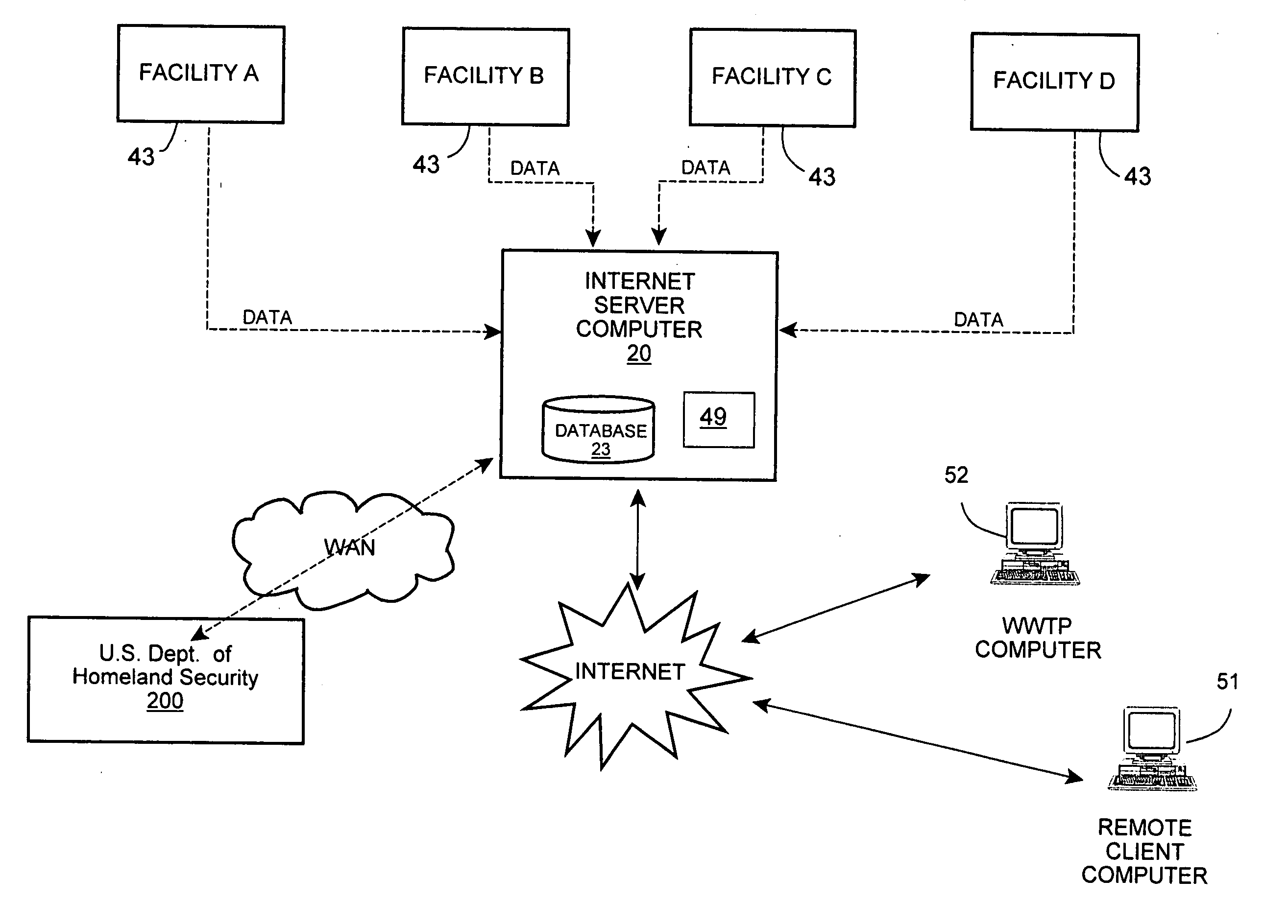
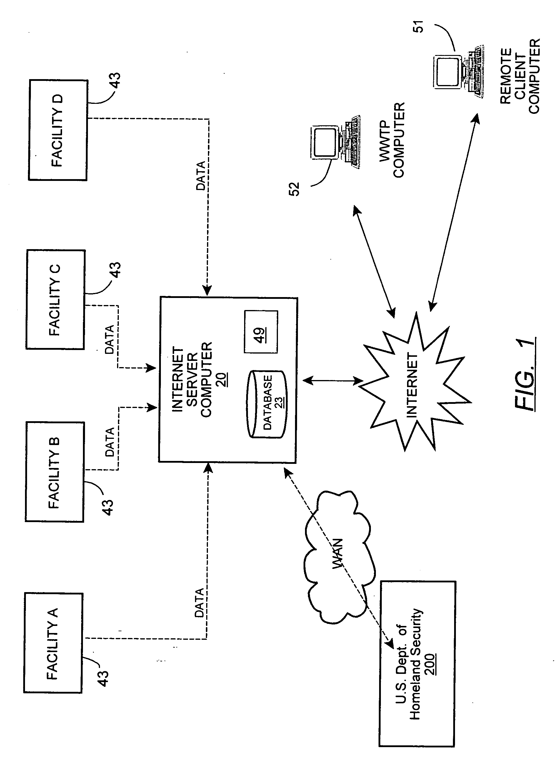
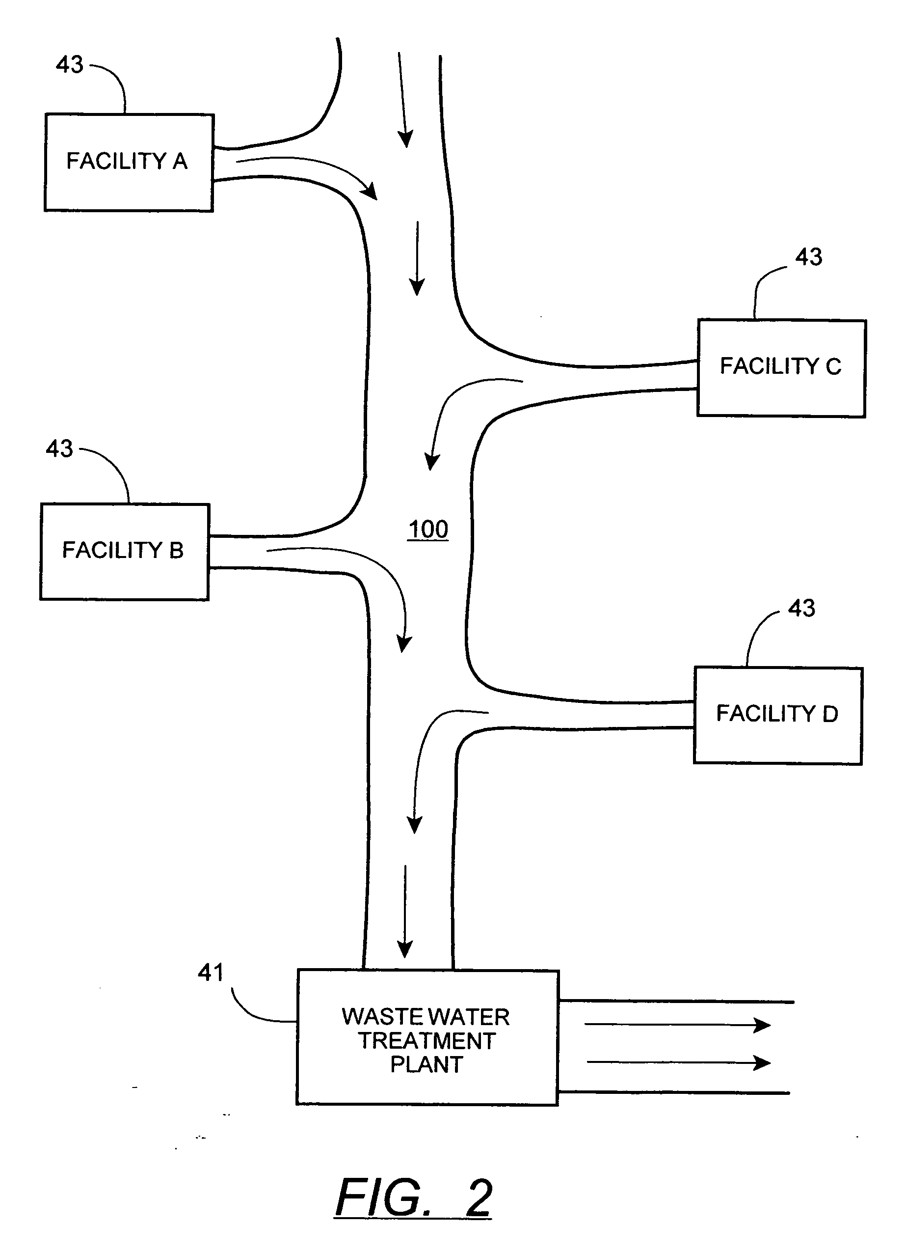
[0030]FIG. 1 illustrates an exemplary network configuration of the system of the instant invention according to a preferred embodiment, with the treatment facilities 43 depicted therein being associated with a central water collection system. FIG. 2 illustrates a typical waste water collection system 100 as is part of the waste water utility infrastructure. The collection system 100 serves numerous end user waste water treatment sites 43 having a central waste water treatment plant (WWTP) 41. In practice, the water treatment sites 43 can include cities, manufacturers, agricultural operations, etc. which treat waste water before it is discharged into the ...


PUM

PropertyMeasurementUnit
transit timeaaaaaaaaaa
compositionaaaaaaaaaa

Abstract

A method for monitoring the composition and flow rate of wastes discharged from industrial waste water treatment facilities into a common collection system for eventual processing at central waste water treatment plant (WWTP). The information is transmitted to a remote computer and stored in a database, and is then analyzed to prepare reports of particular interest to the receiving WWTP or treatment facility. The system includes a data collection and sending unit, a remote Internet Server computer with a database capable of receiving and storing the collected information, and a web server and reporting unit to analyze the data, prepare reports, and send out alarms. It is a further intention of this invention to correlate the incoming data from said industrial waste water treatment plants with known flows and compositions at said central WWTP to predict the flow and composition of influx water at the WWTP.

Description

CROSS REFERENCE TO RELATED APPLICATIONS [0001] This Application is related to U.S. Pat. No. 6,954,701, U.S. pending Application Serial No. Ser. No. 10 / 392,112, filed Mar. 19, 2003, U.S. Pat. No. 6,560,543, and U.S. Pat. No. 6,332,110, the contents of which are each incorporated herein by reference in their entirety.FIELD OF THE INVENTION [0002] This invention is related in general to the field of wastewater treatment and wastewater collection systems, and more particularly to a method of remote monitoring, through a global computer network, the quantity, quality, and composition of waste fluids discharged from distributed treatment sites using control systems, instruments, and sensors having integral processing and communication means. BACKGROUND OF THE INVENTION [0003] The treatment and subsequent recycling of wastewater is a cornerstone of the quality of life in the industrialized world. Cities, industries, and agricultural operations produce large quantities of wastewater, all of...

Claims


Application Information

Patent Timeline
Patent Type & Authority Applications(United States)
IPC IPC(8): B01D35/00
CPCC02F1/008C02F2209/008C02F2209/005
Inventor WOLFE, THOMAS
Owner HACH CO
Why Eureka
Try Eureka