MRAM with split read-write cell structures

Inactive Publication Date: 2007-07-19
HEADWAY TECH INC
View PDF10 Cites 48 Cited by
  • Summary
  • Abstract
  • Description
  • Claims
  • Application Information

AI Technical Summary

Benefits of technology

[0018] A second object of the present invention is to provide a new MRAM cell design that eliminates the tradeoff between a free layer that needs magnetic anisotropy so that it can be an effective storage element and a free layer that has a low switching threshold, so it can be an effective element for the writing of information.
[0019] A third object of this invention is to provide a cell design that eliminates the switching field threshold variations caused by Neel coupling.
[0020] A fourth object of the present invention is to provide a cell design that eliminates switching threshold variations cased by uncompensated edge poles on the free and/or pinned layers.
[0021] These objects will be met by an MRAM design in which the cell free layer is split into two parts, a read sensing layer (layer 1) and an information storage layer (layer 2), where each part of the free layer is formed in a separate portion of the cell. The read sensing layer (layer 1) will have little or no magnetic anisotropy; so it can have an essentially horizontal circular cross-section or an elliptical cross-section of low aspect ratio. Layer

Problems solved by technology

However, if the free layer is given a great deal of magnetic anisotropy, it will hold its magnetization very effectively but it will be increasingly difficult to change that direction when it is required to write upon the cell.
b) The uncompensated magnetic poles at the edges of the pinned layer (ie., the divergence of the magnetization vector at the edges of the layer) produces a bias against th

Method used


Image

  • MRAM with split read-write cell structures
  • MRAM with split read-write cell structures
  • MRAM with split read-write cell structures

Examples


Embodiment Construction

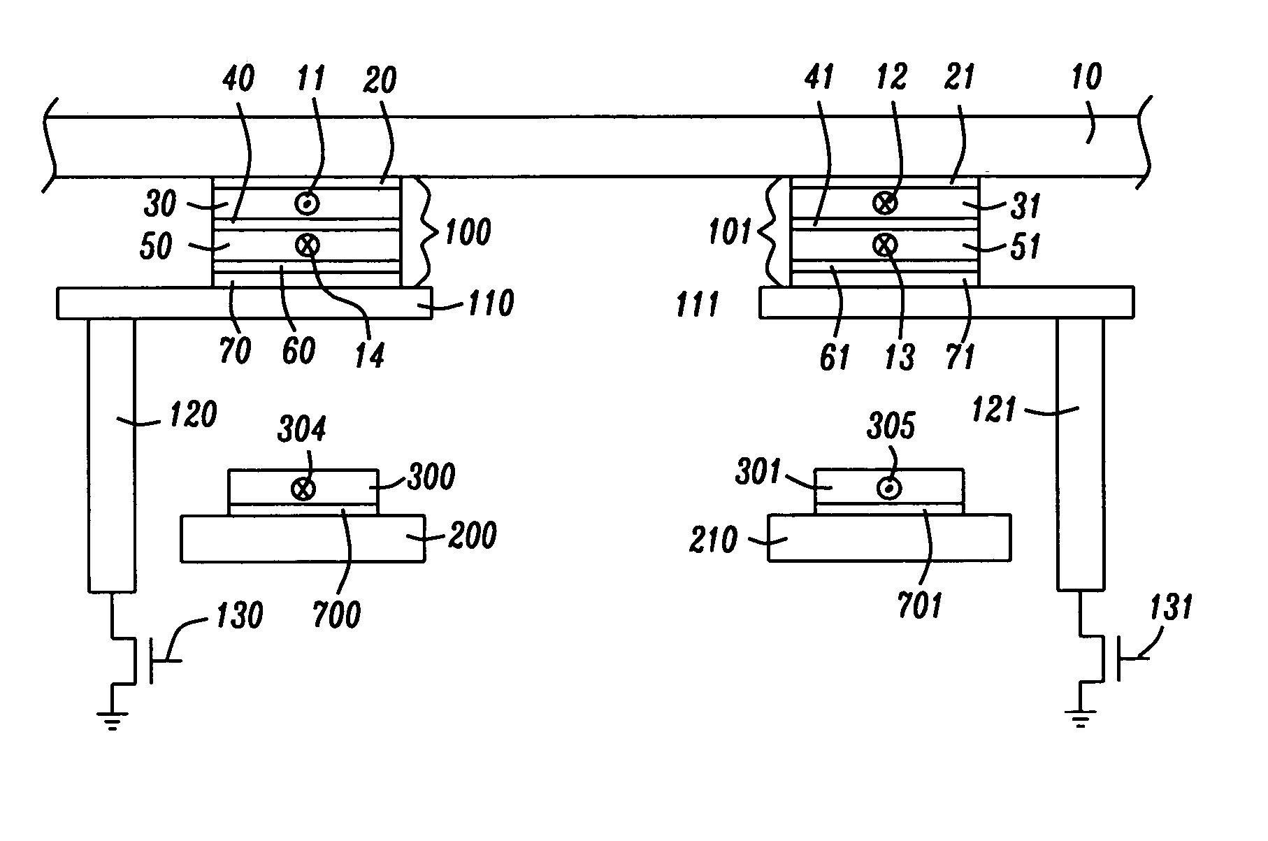
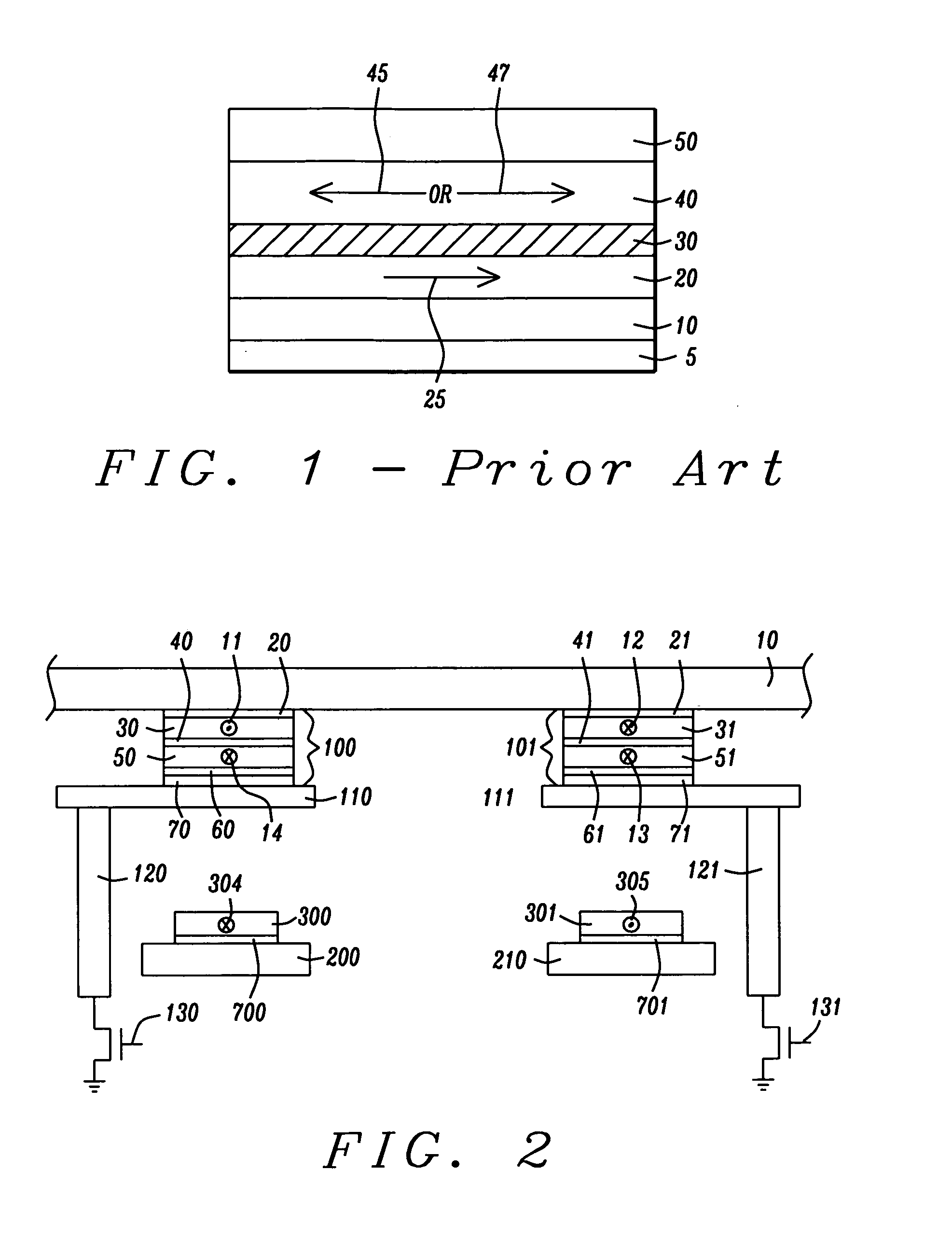
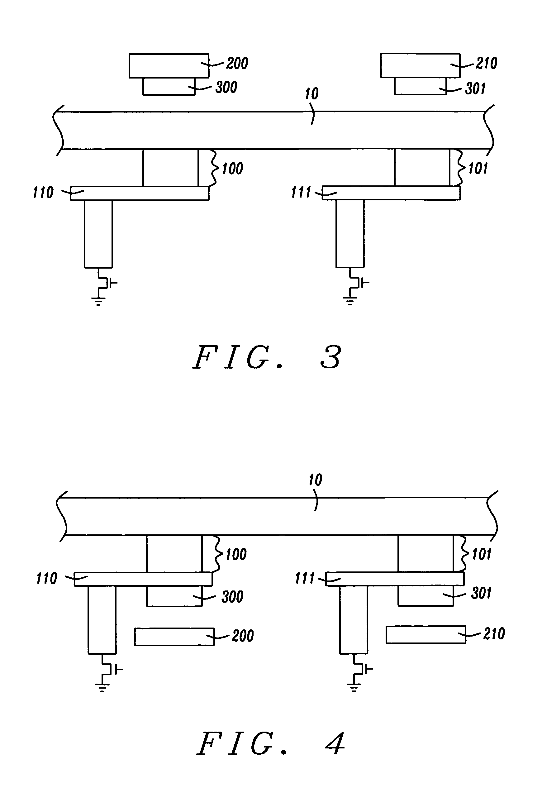
[0031] The preferred embodiments of the present invention are MRAM cells and arrays of such cells, having a free layer that is separated into two parts, each part residing in a separate portion of the cell. The first free layer part (layer 1) has little or no magnetic anisotropy and may even be super-paramagnetic, or, if it does have some degree of magnetic anisotropy, that anisotropy will be associated with an easy axis of magnetization that is perpendicular to the easy axis of magnetization of the second free layer part. The first free layer part and its associated cell portion is used by the MRAM cell and its associated circuitry to read the stored information within the cell. The second free layer part (layer 2) has substantial magnetic anisotropy (in order to maintain a magnetization direction of stored information) and is used within the MRAM cell and associated circuitry to store the information that is subsequently read by layer 1. The second layer need only be located suffi...


PUM


Abstract

An MRAM cell is formed in two separate portions. A first portion, that includes a pinned layer, a tunneling barrier layer and first free layer part, is used to read the value of a stored bit of information. A second portion includes a second free layer part on which information is written and stored. The second free layer part is formed with a high aspect ratio cross-section that renders it strongly magnetically anisotropic and enables it to couple to the relatively isotropic first free layer through a magnetostatic interaction. This interaction aligns the magnetization of the first free layer part in an opposite direction to the magnetization of the second free layer part. The magnetic orientation of the first free layer part relative to that of its adjacent pinned layer determines the resistance state of the first cell portion and this resistance state can be read by passing a current through the first cell portion. Thus, in effect, the first cell portion becomes a remote sensing device for the magnetization orientation of the second free layer part

Description

BACKGROUND OF THE INVENTION [0001] 1. Field of the Invention [0002] This invention relates generally to a magnetoresistive random access memory (MRAM) cell formed in a magnetic tunneling junction (MTJ) configuration and particularly to a form of such cell in which the read and write functions of the cell are assigned to different free layers. [0003] 2. Description of the Related Art [0004] The magnetic tunneling junction (MTJ) device, is a form of giant magnetoresistive (GMR) device in which the relative orientation of uni-directional magnetic moments in parallel, vertically separated upper and lower magnetized layers, controls the flow of spin-polarized electrons tunneling through a very thin dielectric layer (the tunneling barrier layer) formed between those layers. When injected electrons pass through the upper layer they are spin polarized by interaction with the magnetic moment of that layer. The probability of such an electron then tunneling through the intervening tunneling b...

Claims


Application Information

Patent Timeline
IPC IPC(8): H01L43/00
CPCH01L27/228H10B61/22
Inventor MIN, TAIWANG, PO-KANG
Owner HEADWAY TECH INC
Why Eureka
Try Eureka