
Method and system for communicating in cooperative relay networks

a cooperative relay and communication technology, applied in data switching networks, high-level techniques, digital computer details, etc., can solve the problem of not considering the cost of acquiring csi, and achieve the effect of reducing the total power consumption of the network

Active Publication Date: 2007-07-19
MITSUBISHI ELECTRIC RES LAB INC
View PDF8 Cites 118 Cited by
  • Summary
  • Abstract
  • Description
  • Claims
  • Application Information

AI Technical Summary

Benefits of technology

The invention provides a method for selecting a subset of relay nodes and satisfying an outage constraint in a cooperative relay network. The selected relay nodes cooperate to relay data packets from a source node to a destination node in parallel. The invention also describes a protocol for cooperative communication that includes stages of acquiring CSI through feedback and training. The source node broadcasts data packets to the relay nodes, which decode the received data. The relay nodes, based on a relay selection and outage rule, then linearly weight their transmit signals as the data packets are forwarded to the destination node. This process can be characterized as cooperative beamforming by the selected relay nodes. The invention also models the overhead power consumption for acquiring the channel state information (CSI) for beamforming and optimizes a relay cooperation rule for selecting relays that minimize the total power consumption. The model can make trade offs between the number of available nodes, the number of actively relaying nodes, outage probability, and total energy consumed. The invention enables the selection of a minimal number of cooperating relay nodes, at any one time, that minimize total power consumption in the network.

Problems solved by technology

However, they do not consider the cost of acquiring the CSI.

Method used


Image

  • Method and system for communicating in cooperative relay networks
  • Method and system for communicating in cooperative relay networks
  • Method and system for communicating in cooperative relay networks

Examples


Embodiment Construction

[0032] Cooperative Relay Network

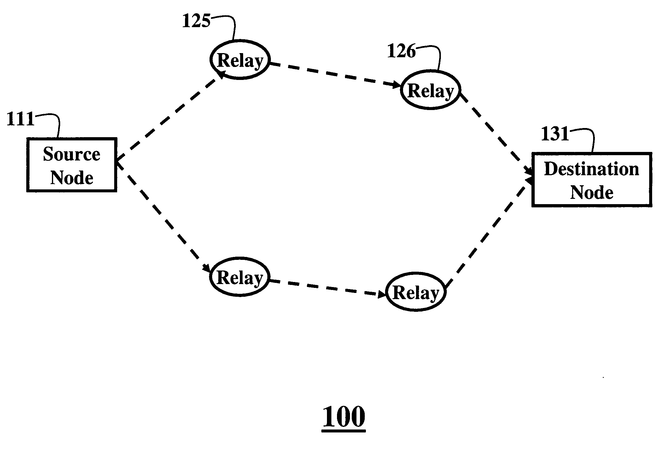
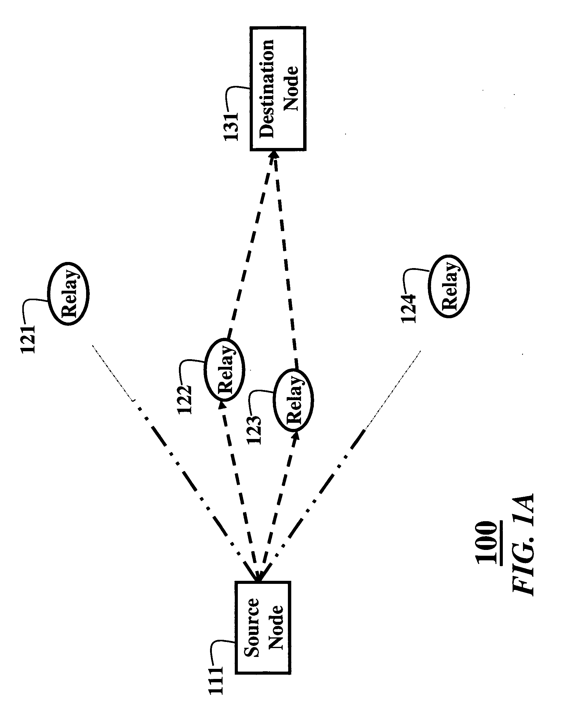
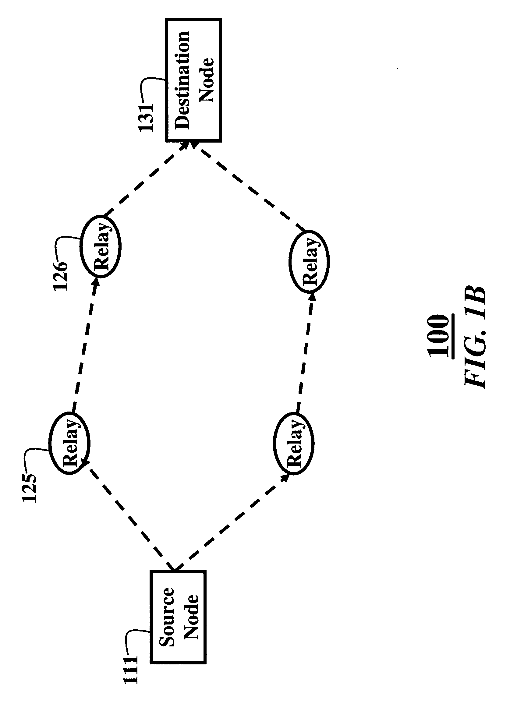
[0033]FIGS. 1A and 1B show communications networks 100 according to an embodiment of our invention. It is desired to minimize power consumption in the network while sending data packets. The method includes training 10 and operational 20 phases, see FIG. 2. In one embodiment of the invention the phases 10 and 20 are combined.

[0034] The cooperative relay network 100 includes a source node 111, a set of N relay nodes 121-126, and a destination node 131, i.e., source, relays, and destination, respectively. All channels between all nodes are frequency non-selective channels that undergo independent Rayleigh fading.

[0035] Therefore, the channel power gains hi from the source to the set of relays, and the channel power gains gi from the set of relays to the destination are modeled as independent, exponentially distributed random variables with means hi and gi, respectively, where i=1, . . . , N. The mean channel power gains depend on a distance between t...


PUM


Abstract

A method and system for communicating information in a cooperative relay network of wireless nodes. The wireless nodes including a source, a set of relays, and a destination. Channel state information for each channel between a particular relay of the set of relays and the destination is estimated. A subset of the relays is selected based on the channel state information. The channel state information is fed back to the subset of relays. The source node can then broadcasting data packets from the source to the subset of relays, and the subset of relays forward coherently the data packets from the subset of relays to the destination using beamforming based on the channel state information, while adjusting power to minimize a total energy consumption in the network.

Description

FIELD OF THE INVENTION [0001] This invention relates generally to wireless communications networks, and more particularly to communicating in a cooperative relay network with fading channels. BACKGROUND OF THE INVENTION [0002] In conventional relay networks, data packets are transmitted from a source node to a destination node via a single path with, perhaps, multiple serial hops through relay nodes. [0003] In a cooperative relay network, wireless nodes cooperate with each other in transmitting data packets in parallel. By exploiting the broadcast nature of a wireless channel to reach multiple relay nodes simultaneously, and by enabling the relay nodes to cooperate, it is possible to reduce energy consumption in delivering a packet from the source to the destination. This can also significantly increase gains in overall throughput and energy efficiency, A. Nosratinia, T. Hunter, and A. Hedayat, “Cooperative communication in wireless networks,” IEEE Communications Magazine, vol. 42, ...

Claims


Application Information

Patent Timeline
Patent Type & Authority Applications(United States)
IPC IPC(8): H04Q7/24H04W40/06H04W52/46
CPCH04B7/026H04B7/0408Y02B60/50H04W52/46H04W40/06Y02D30/70
Inventor MEHTA, NEELESH B.MADAN, RITESHMOLISCH, ANDREAS F.ZHANG, JINYUN
Owner MITSUBISHI ELECTRIC RES LAB INC
Learn More