
Ambulatory infusion membrane pump

a membrane pump and ambulatory technology, applied in the direction of positive displacement liquid engine, process and machine control, instruments, etc., can solve the problems of high cost of hospitals, complicated check valve arrangement of cassette, and many of these pumps are very sophisticated and sometimes very complicated

Inactive Publication Date: 2007-07-19
MEDUX AB
View PDF20 Cites 70 Cited by
  • Summary
  • Abstract
  • Description
  • Claims
  • Application Information

AI Technical Summary

Benefits of technology

[0012] The present invention is a membrane pump consisting of two main bodies: the computer with its housing and the administration set. The membrane pump works distinctly with equal membrane movements repeated as a decided position of the stroke. A rotational electric motor with a gear is positioned in the housing, and the outgoing shaft moves a screw in connection with a threaded plunger rod and at the other end in connection with the membrane tap. At the end cover on the housing the membrane pump is snapped into an attachment consisting of a guide rail and a shoulder on the pump house, which easily is snapped on when the pump house is in exact position. The electrical motor has a permanent magnet and a sensor which registrates each revolution of the motor and communicates signals to the computer, which registers each signal in forward respectively backward mode of the driving motor, thus counting each revolution and registers the exact position of the screw on the plunger rod.
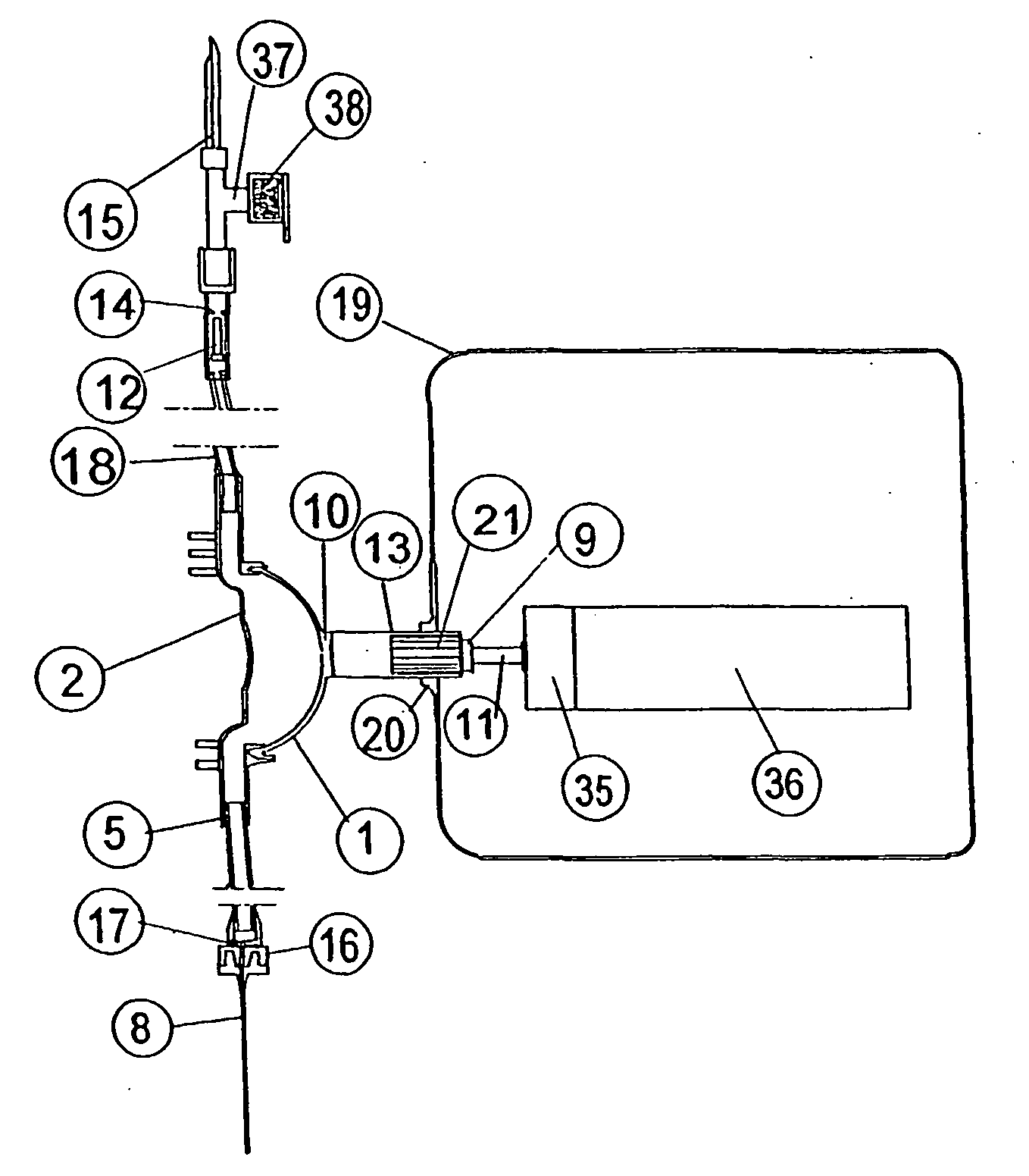
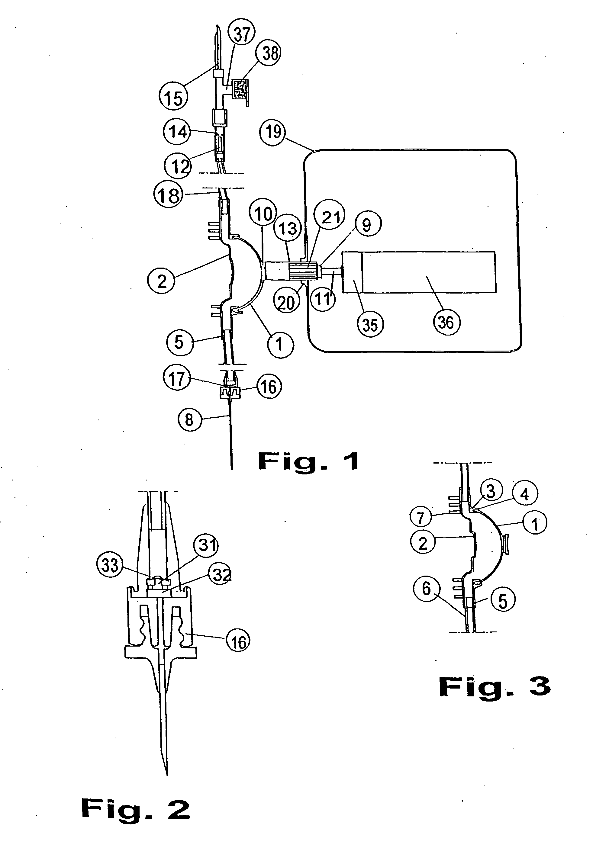
[0014] In a system with tubes and pump, elastic effects can arise, for instance when the pump suddenly is cut off (which happens when the polarity reversal activates for intended reversal of the plunger rod). When the pressure leaves the system, elastic effects arise; the volume of the system decreases. In order to prevent unintended through flow in the system according to such elastic effects, check valves are positioned in each end of the tubing; the inflow check valve close to the fluid container and the outflow check valve close to the needle arrangement.

Problems solved by technology

Many of these pumps are very sophisticated and sometimes very complicated, as U.S. Pat. No. 5,482,438 and very expensive for the hospitals.
However the cassette is with its arrangements of check valves a little bit complicated, and the amount of material in the cassette is significantly high.
When initially filling up the pump, de-airing obviously will become problematic.
Document U.S. Pat. No. 4,846,636 describes a piston pump with a complicated construction, where it is very difficult to de-air a pumped fluid In a controlled way.
This pump has a large dead space, which means that a substantial amount of fluid is interlocked into the pump when a pumping operation is ended.
A careful control of the pumped amount of fluid by use of different piston stroke lengths are not possible in any of the designs of U.S. Pat. No. 4,846,636 and WO 99 / 21596.

Method used


Image

  • Ambulatory infusion membrane pump
  • Ambulatory infusion membrane pump
  • Ambulatory infusion membrane pump

Examples


Embodiment Construction

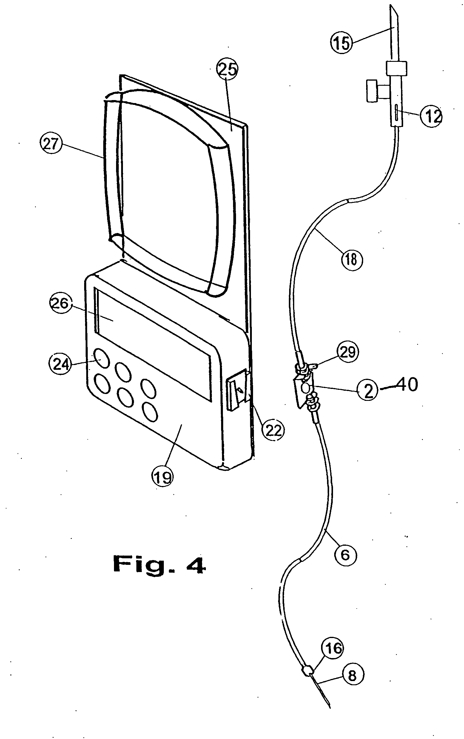
[0030] The exemplary embodiment of the membrane pump of the present invention, indicated generally as the pump house 2 in FIG. 1 with the membrane 1 and connected to an inlet tube 18 and outlet tube 5, with inlet check valve 14 and outlet check valve 16, and an attachment to the injection needle 8. The liquid container is penetrated by the insert mouthpiece 15 which is connected to the inlet check valve house 14 and with a cone 12, which floats, movable longitudinally in the house 14. The air filter 38 is connected to the inlet tube 15. The device box 19 is schematic drawn and contains an electric motor 36 with gear box 35 and a screw 11 which when rotated moves the threaded piston 9 longitudinally and the elongation of the piston 13 which presses the membrane inwards and lets the membrane 1 free for recoiling, whereas the membrane pump is filled with liquid. The elongation 13 of the piston 9 has splines 21 which fit in corresponding tapping in the gablesocket 20 in the device box 1...


PUM


Abstract

Ambulatory membrane pump intended for medical use e.g. for infusion purposes, consisting of two main parts: 1) the basic device with motor drive and computer, and 2) the administration set, which is disposable. The arrangement with check valves in both ends of the administration system safeguards that no leakage happens when gravitational forces are acting, due to height differences between fluid bag and needle.

Description

TECHNICAL FIELD [0001] The present invention relates to fluid injection pumps with disposable membrane pump and tubing intended for injection of medicines, pain relief and fluids related to nursing. BACKGROUND OF THE INVENTION [0002] Membrane injection pumps are used in many applications, as ultra small plastic pumps intended for medical applications. However, when used for portioning fluids, as medicines, with a high degree of precision, usually other pumping methods dominate the market. Such pumps are syringe or plunger pumps, as well as peristaltic pumps. [0003] Transporting fluids from a container to an injection needle with a high degree of precision is claimed as to the dosage, especially concerning new, potent medicines. Not intended leakage through tubing arrangement must be safely restricted, as when a container filled with medicine is placed above the needle, the static pressure can generate a flow if the system is not restricted against this. [0004] Examples of prior art ...

Claims


Application Information

Patent Timeline
IPC IPC(8): F04B43/08A61M5/142A61M5/00A61M5/162A61M5/168
CPCA61M5/14224A61M5/16809A61M5/162
Inventor NILSON, BILLY
Owner MEDUX AB
Learn More