Structure assessment using spatial-frequency analysis

a spatial frequency analysis and structure technology, applied in the direction of measurement using nmr, instruments, applications, etc., can solve the problems of increasing the risk of fracture in vulnerable regions, the threat to the health of the elderly, and the cost of productivity loss billions more, so as to reduce the risk of fractures in vulnerable regions, and the risk of fractures is increased

Inactive Publication Date: 2007-07-19
OSTEOTRONIX MEDICAL PTE LTD
View PDF31 Cites 35 Cited by
  • Summary
  • Abstract
  • Description
  • Claims
  • Application Information

AI Technical Summary

Problems solved by technology

The Impact of Bone Disease Diseases of the skeletal system, including osteoporosis and other less common conditions, are a major threat to the health of the elderly, particularly women.
More than 1.5 million fractures occur each year as a result of osteoporosis, with direct costs of care of approximately $15 billion, and billions more in costs associated with loss of productivity and the three-fold increase in risk of mortality associated with fractures.
The loss of bone strength that results from the thinned and more porous bone structure in osteoporotic bone increases the risk of fracture in vulnerable regions such as the hip and spine.
Although the hip and spine exhibit most of these fractures, they are more difficult to image than the calcaneous (heel bone) and distal radius.
Other forms of hormone therapy also stimulate development of bone but carry significant risk of side effects as shown in recent clinical trials.
Recent studies in the USA have indicated that DEXA is underutilized, with less than 25% of the at-risk population receiving BMD testing, due partially to the cost of DEXA but primarily to lack of awareness.
Of much greater concern is the fact that physicians have begun to question the clinical relevance of DEXA, based on emerging evidence that DEXA measurements do not properly predict fracture risk and are particularly inadequate in assessing the effectiveness of therapy.
But the high cost of high-field systems, and the need for long acquisition times in order to resolve fine structures combined with the requirement that the patient (imaged body part) not move during acquisition, yield a level of impracticality in the implementation of standard MRI for this purpose.
However that application does not disclose the necessity of windowing or of the use of a readout gradient to obtain a line in k space in one epoch.

Method used


Image

  • Structure assessment using spatial-frequency analysis
  • Structure assessment using spatial-frequency analysis
  • Structure assessment using spatial-frequency analysis

Examples


Embodiment Construction

[0037] As noted above, this application claims priority on two provisional applications. The first provisional describes a technique and apparatus for characterizing the size distributions of a dispersed NMR signal producing phase intermingled with one or more additional phases with significantly different signal properties. Examples are marrow in cancellous bone and petroleum dispersed in strata.

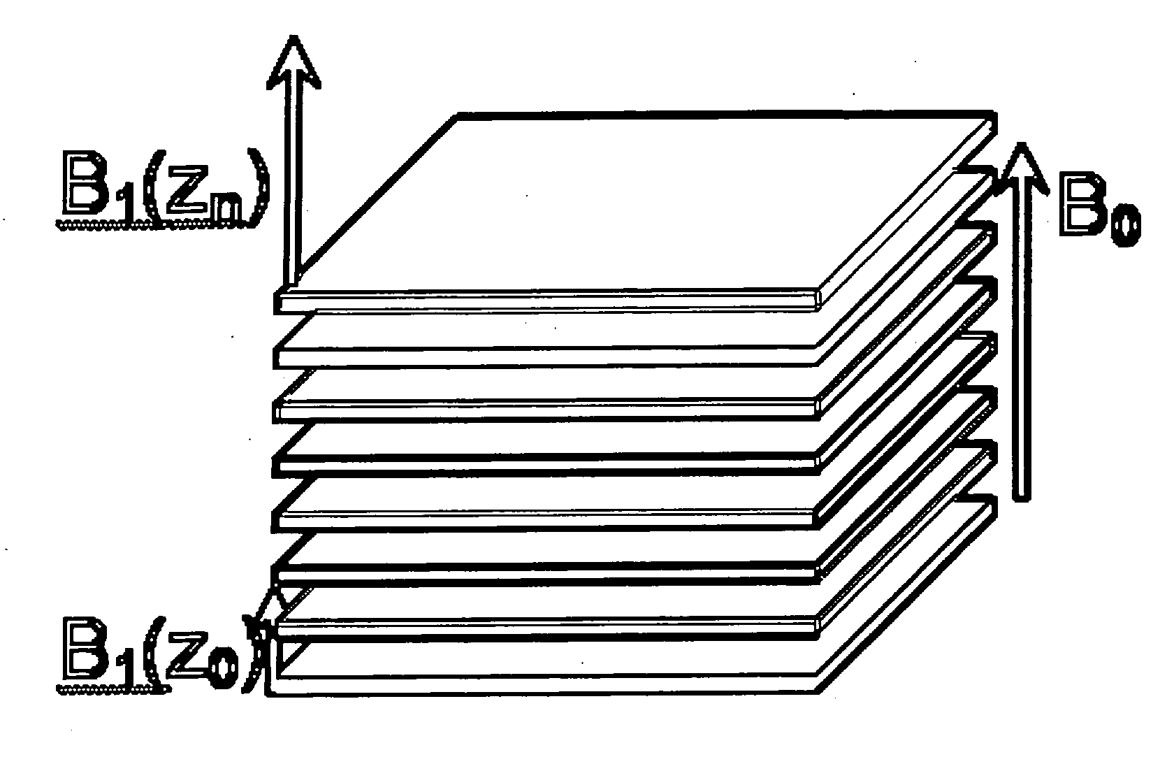
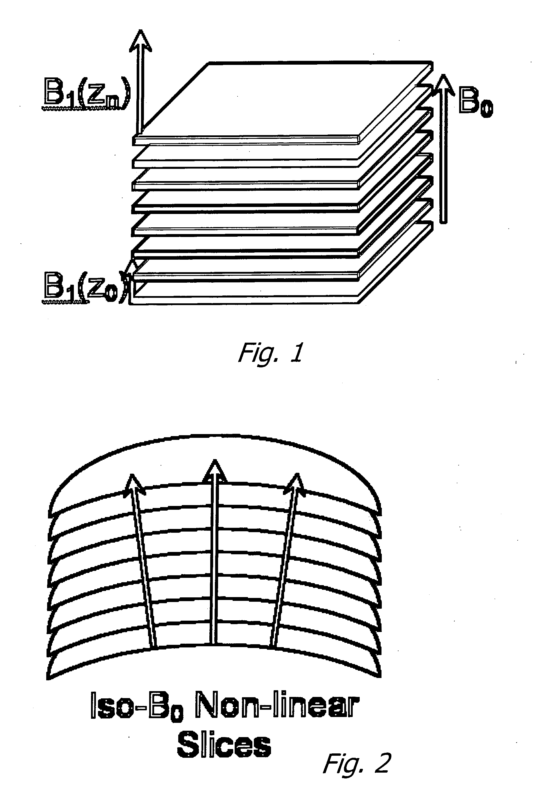
[0038] The approach involves the following components: First, provide a magnetic field (B0) covering the region of interest (ROI) in a sample desired to be characterized. Second, provide a gradient in B0 over the ROI. Third, provide transmit (excitation) and receive antennas / systems that have a net high sensitivity to signals excited in and emanating from the ROI.

[0039] Using this apparatus, perform an NMR experiment by transmitting a defined bandwidth pulse to excite the NMR signal in the desired range of B0, followed by one or more refocusing transmit pulses and sampling of the received...


PUM


Abstract

The disclosed innovation is a method for acquiring spatial frequency spectra from specific locations in a 3D sample using modifications of the current MRI techniques for localized NMR spectroscopy. The innovation in its simplest abstraction is to add the use of a read out gradient to the current NMR spectroscopy pulse sequences and record the resultant echo. These techniques generate spectra from a selected region or generate an image of the results over a region of the sample. These methods can be applied to analyzing the structure of trabecular bone as well as for analyzing or diagnosing disease in cases where there is a difference in the spatial frequency power spectrum due to physiologic or disease processes. Various embodiments are disclosed.

Description

CROSS-REFERENCE TO RELATED APPLICATION [0001] This application claims the benefit of U.S. Provisional Patent Application No. 60 / 597,349 filed Nov. 27, 2005 and also claims the benefit of U.S. Provisional Patent Application No. 60 / 743,779 filed Mar. 25, 2006.BACKGROUND OF THE INVENTION [0002] 1. Field of the Invention [0003] The present invention relates to the field of diagnostic assessment of complex biological and physical structures, including bone strength in patients at risk of or suffering from osteoporosis and other conditions that degrade the trabecular structure of cancellous bone. Additional structures include evaluating vasculature in tumors, and hydrocarbon pore distributions in strata. [0004] 2. Prior Art [0005] The trabecular architecture is both highly sensitive to metabolic changes in bone (relative to the more dense outer shell of cortical bone) and a major contributor to the overall strength of a bone. Hence it is an appropriate surrogate marker for tracking diseas...

Claims


Application Information

Patent Timeline
Patent Type & Authority Applications(United States)
IPC IPC(8): A61B5/05
CPCA61B5/055A61B5/4504A61B5/7257G01R33/485G01R33/46G01R33/4833A61B5/726G01R33/483
Inventor JAMES, TIMOTHY W.CHASE, DAVID
Owner OSTEOTRONIX MEDICAL PTE LTD
Why Eureka
Try Eureka