
Cardiac output measurement devices and methods

a technology for measuring devices and patients, applied in the field of patient cardiovascular system measurement devices and methods, can solve the problems of high risk of infection, discontinuous or interrupted data collection, lack of precision, etc., and achieve the effect of minimizing infection risk and discomfort for patients, reducing cross-sectional dimensions of the portion of the device inside the patient, and reducing the risk of infection

Inactive Publication Date: 2007-07-19
LOPEZ GEORGE
View PDF55 Cites 2 Cited by
  • Summary
  • Abstract
  • Description
  • Claims
  • Application Information

AI Technical Summary

Benefits of technology

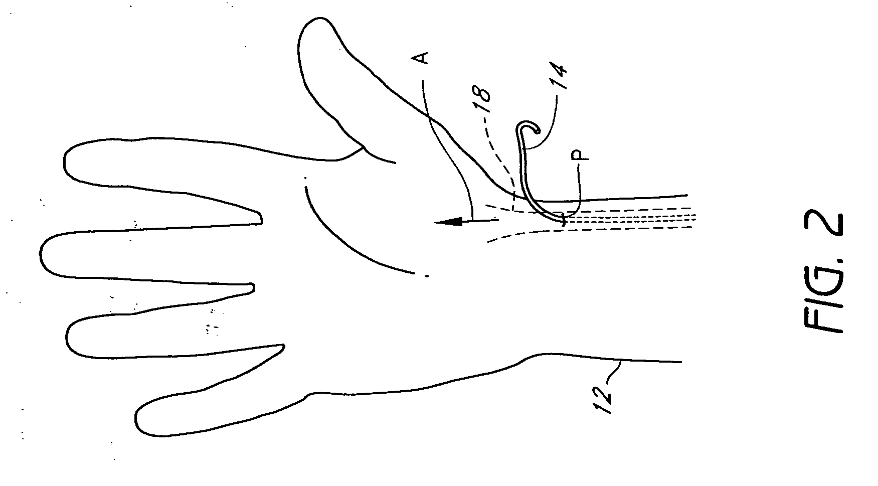
[0010] Some embodiments of the present inventions include a blood measuring component with an energy producing element, a temperature sensing element, elongate electrical leads connected to each of these elements, and one or more coatings (such as electrical or thermal insulator coatings) surrounding at least a portion of the elements and / or leads. A catheter body is generally not required to support the electrical components or lead wires. As a result, the cross-sectional dimensions of the portion of the device inside of the patient can be greatly reduced in comparison to typical thermodilution catheters. In addition, smaller blood vessels can be utilized, such as the radial artery, for example. Furthermore, the risk of infection can be greatly reduced because the portion of the blood measuring component that passes through the skin of the patient is generally much smaller than in a typical thermodilution method. In such an arrangement, the device can be implanted for relatively long periods of time with minimized risk of infection and discomfort to the patient. Moreover, the patient's pain upon insertion and the discomfort of prolonged usage can be significantly diminished.
[0011] In some embodiments of a cardiac output measuring device, the blood measurement component or probe includes an energy producing element and a first pair of lead wires configured to transmit electric current through the energy producing element. The device also can include a temperature sensing element and a second pair of lead wires configured to transmit electric current through the temperature sensing element. At least one coating can be configured to electrically insulate each wire of the first and second pairs of lead wires from one another. The coating(s) can provide electrical insulation of the lead wires, energy producing element, and / or temperature sensing element. The coating(s) can also impart a desired degree of stiffness to the blood measurement component to achieve a particular positioning or orientation of the component within the blood vessel. The coatings(s) can also include one or more substances that produce or enhance antimicrobial or anticoagulant effects. The first and second pairs of lead wires can be secured in an elongate bundle.

Problems solved by technology

However, the existing methods suffer from one or more disadvantages, including lack of precision, discontinuous or interrupted data collection, high risk of infection, and significant discomfort and inconvenience to the patient.
For example, if thermodilution catheters remain within the patient for an extended period of time, the risk of infection becomes significant.
It has been estimated that the cost of treating infections caused by thermodilution catheters can be many times the combined cost of the catheter and the implantation procedure.
Furthermore, while the thermodilution catheters are in place, the mobility of the patients may be significantly restricted.
In addition, the presence of a catheter for an extended period of time is likely to be uncomfortable for the patient because the diameter of the catheter is typically relatively large in comparison with the diameter of a blood vessel.
The large size of the catheter can also cause trauma, damage, and other interference within the vessel by contacting internal issues and impeding blood flow.
Accordingly, the use of whole body oxygen consumption to estimate cardiac output may lead to undesirable errors and delays in the reporting of cardiac output events.

Method used


Image

  • Cardiac output measurement devices and methods
  • Cardiac output measurement devices and methods
  • Cardiac output measurement devices and methods

Examples


Embodiment Construction

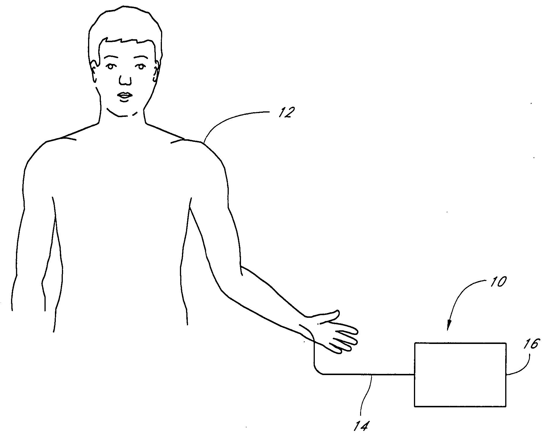
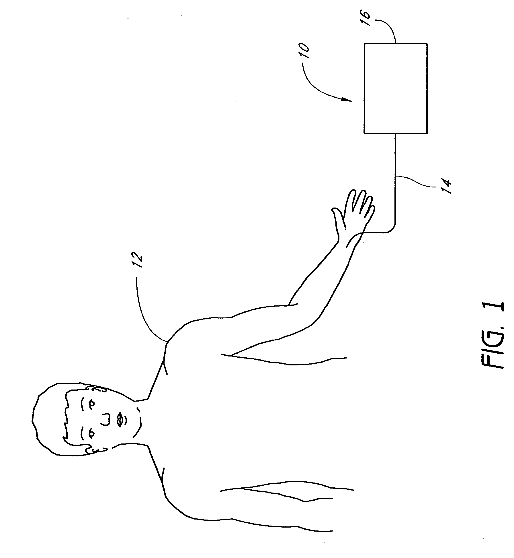
[0023]FIGS. 1-5 illustrate embodiments of cardiac output measurement devices. With reference to FIG. 1, the cardiac output measurement device 10 is configured for use in monitoring the cardiac output of a patient 12. The device 10 includes a probe 14 connected to a controller 16. The probe 14 is introduced within the vasculature of the patient 12 and is configured to detect certain parameters of the blood within the vasculature of the patient 12. Data collected by the probe 14 is communicated to the controller 16, which utilizes the data to calculate the cardiac output of the patient 12 and / or other desired physiological parameters of the patient 12. Furthermore, the controller 16 can be configured to send control signals to the probe 14, as described in further detail below.

[0024] The probe 14 is configured to produce a temperature change to the blood within the vasculature of the patient 12, which generally involves adding heat energy to the blood. The controller 16 communicates ...


PUM


Abstract

A device for measurement of cardiac output including an elongate body and a plurality of electrical components, including at least an energy producing element, such as a heating coil, and a temperature sensing element, such as a thermistor. The elongate body includes a plurality of electrical lead wires configured to transmit electric current to the electrical components and at least one insulation layer configured to electrically insulate the plurality of lead wires from one another. Preferably, a cross-sectional size of the elongate body is generally equal to a combination of the cross-sectional size of the plurality of lead wires and a cross-sectional size of the at least one insulation layer. In a preferred method of use, the device is introduced into the radial artery of a patient.

Description

CROSS-REFERENCE TO RELATED APPLICATION [0001] This application claims the benefit of U.S. Provisional Application No. 60 / 740,543, filed Nov. 29, 2005, which is incorporated by reference in its entirety.BACKGROUND OF THE INVENTIONS [0002] 1. Field of the Inventions [0003] The present inventions relate to devices and methods for measurement of the cardiovascular system of a patient. More specifically, the present inventions relate to devices and methods for measuring cardiac output and, in some arrangements, measuring other blood parameters. [0004] 2. Description of the Related Art [0005] The monitoring of cardiac output is a common diagnostic technique used to evaluate the heart function and fitness of a patient. Cardiac output is sometimes defined as the volume of blood pumped by the heart over a period of time and is typically expressed in units of liters per minute (L / min.). Multiple techniques exist to measure or estimate cardiac output. However, the existing methods suffer from ...

Claims


Application Information

Patent Timeline
Patent Type & Authority Applications(United States)
IPC IPC(8): A61B5/00
CPCA61B5/0002A61B5/029A61B5/028
Inventor LOPEZ, GEORGE
Owner LOPEZ GEORGE
Learn More