Chemical reactor and fuel cell system

Inactive Publication Date: 2007-07-26
KK TOSHIBA
View PDF2 Cites 5 Cited by
  • Summary
  • Abstract
  • Description
  • Claims
  • Application Information

AI Technical Summary

Benefits of technology

[0012]An object of the present invention is to provide a chemical reactor and a fuel cell system, which are capable of inhibiting the leakage of unreacted gas as well as the leakage of a gas containing a by-product.
[0016]According to a fourth aspect of the present invention, there is provided a fuel cell system comprising: a vessel for housing an organic raw material having a higher saturated vapor pressure than atmospheric pressure; a reformer constituted by a vaporization section for vaporizing the organic raw material, by a reforming section for reforming the organic raw material thus vaporized into a hydrogen-containing gas, and by a carbon monoxide-removing section for removing at least a portion of carbon monoxide included in the hydrogen-containing gas; an inlet flow channel to which the vessel is removably attached, enabling the vessel to be communicated with the reformer; a cut-off valve disposed in the inlet flow channel and designed to be brought into an open state as the pressure in the inlet flow channel becomes the same with or higher than a predetermined pressure, thus permitting the organic raw material to pass through the inlet flow channel, and brought into a closed state as the pressure in the inlet flow channel becomes lower than said predetermined pressure, thus cutting off inlet flow channel; a fuel cell unit for generating electrical energy by making use of the hydrogen-containing gas having said at least a portion of carbon monoxide removed therefrom and air including oxygen; and a combustion device for burning at least a portion of exhaust gas discharged from the fuel cell unit.

Problems solved by technology

In the actual use of these small power sources, depending on the environments of use or on the manner of handling them, they may suffer a severe shock if the body of this power source is accidentally dropped.
When the connection between a vessel housing the fuel and a power source main body is damaged or when the vessel is disconnected from the power source main body due to such a severe shock, the sealing performance of the power source may be damaged, possibly permitting the substance contained in the power source main body or in the vessel to leak therefrom into the atmosphere.
However, according to the fuel cell system of the patent document 1, it is impossible to sufficiently inhibit the leak-out of fuel gas to the atmosphere from the interior of the system.

Method used


Image

  • Chemical reactor and fuel cell system
  • Chemical reactor and fuel cell system
  • Chemical reactor and fuel cell system

Examples


first embodiment

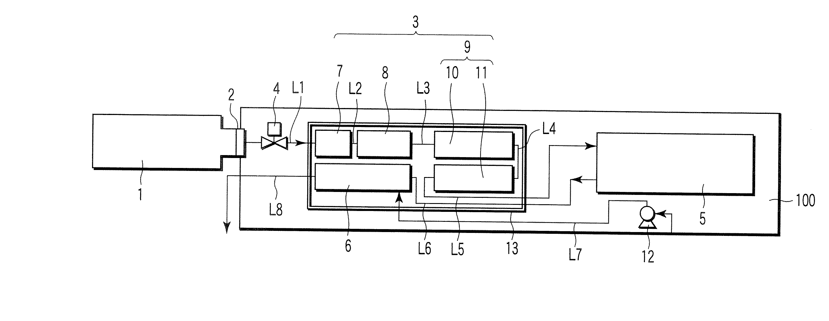
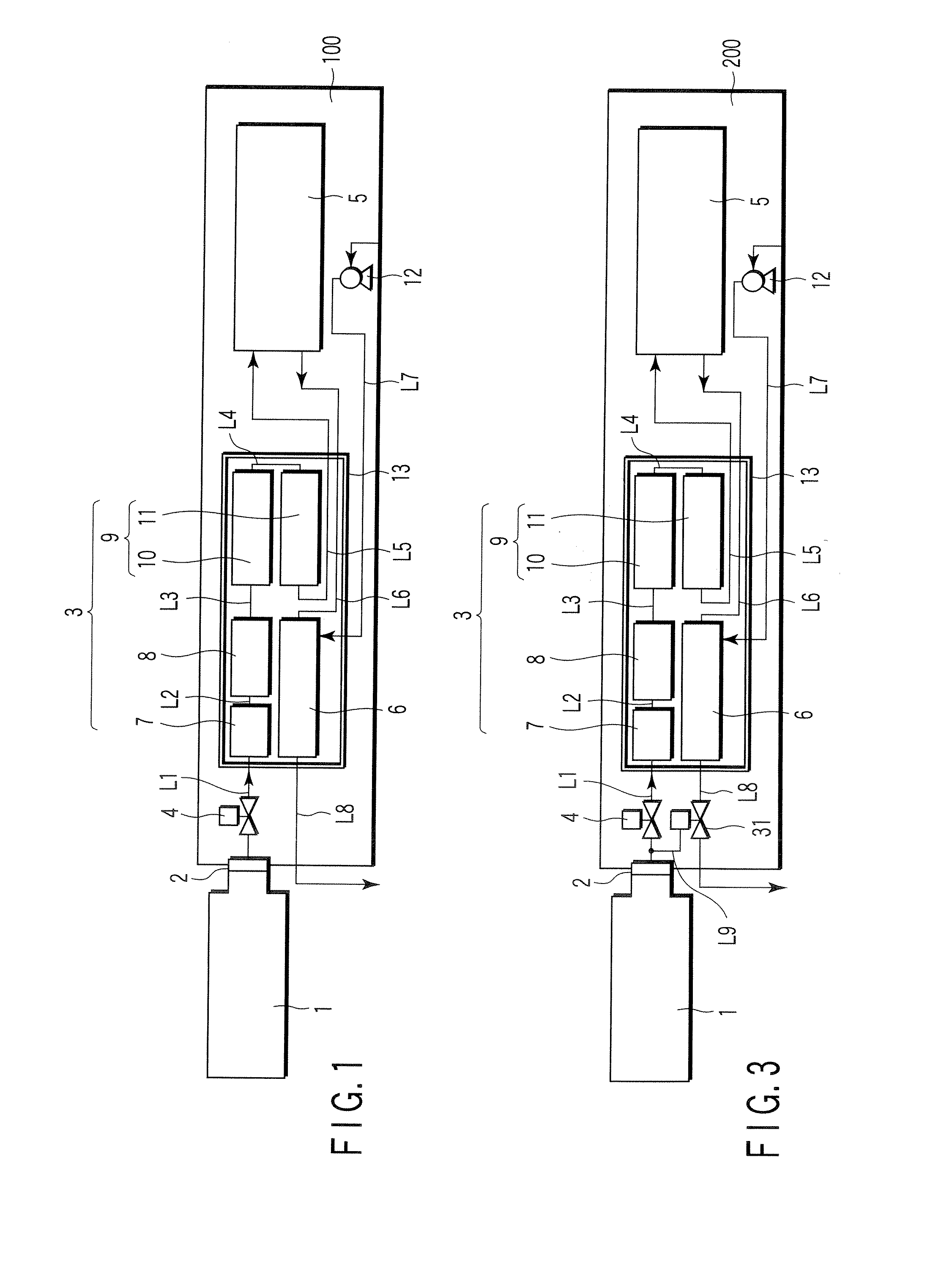
[0031]The fuel cell system according to the first embodiment of the present invention will be explained with reference to FIG. 1. This fuel cell system comprises a system main body 100, a fuel vessel 1, and a connecting portion 2 for removably connecting the fuel vessel 1 with the system main body 100. This system main body 100 is equipped with a reformer 3, an inlet side cut-off valve 4, a fuel cell unit 5 acting as a reformer, and a combustion equipment 6. The reformer 3 is constituted by a vaporizing section 7, a reforming section 8 and a CO-removing section 9. This CO-removing section 9 is constituted by a CO-shifting section 10 and a methanation section 11. The combustion equipment 6 is connected with an air pump 12.

[0032]The fuel vessel 1 is removably connected, via the connecting portion 2, with a pipe line (hereinafter referred to as an inlet port line L1) communicated with the inlet port side of the vaporizing section 7. The fuel vessel 1 is filled with, as a fuel for the f...

second embodiment

[0055]Next, a fuel cell system according to the second embodiment of the present invention will be explained with reference to FIGS. 3, 4A and 4B. Incidentally, with respect to the components or parts of this embodiment which overlap with those of the first embodiment, the explanations thereof will be omitted in the following description.

[0056]As shown in FIG. 3, the fuel cell system according to the second embodiment is featured in that an outlet side cut-off valve 31 is additionally mounted on the fuel cell system of the aforementioned first embodiment. This outlet side cut-off valve 31 is attached to the outlet line L8 which is employed for discharging the exhaust gas from the combustion device 6 out of the fuel cell system main body 200. The exhaust gas generated in the combustion device 6 is discharged out of the fuel cell system through the outlet side cut-off valve 31. Due to the effect of the pressure of fuel, which is higher than atmospheric pressure on the pressure-actuati...

third embodiment

[0065]Next, a fuel cell system according to the third embodiment of the present invention will be explained with reference to FIG. 5. Incidentally, with respect to the components or parts of this embodiment which overlap with those of the above-described embodiments, the explanations thereof will be omitted in the following description.

[0066]The dividing-flow type cut-off valve shown in FIGS. 4A and 4B can be used not only in the outlet port side flow channel but also in the inlet port side flow channel. In the fuel cell system of this embodiment, a dividing-flow type cut-off valve is employed as an inlet side cut-off valve. In FIG. 5, the reforming unit 51 is an integral body comprising, as shown in FIGS. 1 and 3, a vaporizing section 7, a reforming section 8, a CO shifting section 10, a methanation section 11, a combustion device 6, and, if required, a heat-insulating member 13.

[0067]In the fuel cell system according to the third embodiment, a control valve 52 for controlling the ...


PUM


Abstract

There is proposed a chemical reactor comprising a vessel for housing an organic raw material having a higher saturated vapor pressure than atmospheric pressure, a reformer for reforming at least a portion of the organic raw material into a reformed gas, an inlet flow channel to which the vessel is removably attached, enabling the vessel to be communicated with the reformer, and an inlet port side cut-off valve disposed in the inlet flow channel and designed to be brought into an open state as the vessel is attached, thus permitting the organic raw material to pass through the inlet flow channel, and brought into a closed state as the vessel is removed from the inlet flow channel, thus cutting off the inlet flow channel.

Description

CROSS-REFERENCE TO RELATED APPLICATIONS[0001]This application is based upon and claims the benefit of priority from prior Japanese Patent Application No. 2006-015233, filed Jan. 24, 2006, the entire contents of which are incorporated herein by reference.BACKGROUND OF THE INVENTION[0002]1. Field of the Invention[0003]This invention relates to a chemical reactor and a fuel cell system.[0004]2. Description of the Related Art[0005]In recent years, there has been an increasing expectation for the development of a fuel cell system using hydrogen and an ultramicro-gas turbine system which are considered useful as a small power source for portable electronic instruments for supporting the information society.[0006]As for the fuel to be employed in these systems, dimethyl ether is especially considered promising. Dimethyl ether can be easily liquefied. Since the saturated vapor pressure of dimethyl ether at ordinary temperature, once it is liquefied, is about 6 atm, which is much higher than...

Claims


Application Information

Patent Timeline
IPC IPC(8): B01J8/00
CPCB01J8/0438Y02E60/50C01B3/323C01B3/586C01B2203/0233C01B2203/0283C01B2203/0445C01B2203/047C01B2203/066C01B2203/067C01B2203/0822C01B2203/0827C01B2203/1035C01B2203/1211H01M8/0618H01M8/0662B01J8/0492Y02P20/10
Inventor KITAMURA, HIDEOISOZAKI, YOSHIYUKIKUWATA, MASAHIRO
Owner KK TOSHIBA
Why Eureka
Try Eureka