Tissue penetration device

a tissue and needle technology, applied in the field of needle sampling devices, can solve the problems of slow response time, undesirable to continue to pull the needle, and discourage patients from testing, and achieve the effect of reproducing spontaneous blood samples reliably, repeatedly and painlessly

Inactive Publication Date: 2007-07-26
SANOFI AVENTIS DEUT GMBH
View PDF99 Cites 281 Cited by
  • Summary
  • Abstract
  • Description
  • Claims
  • Application Information

AI Technical Summary

Benefits of technology

[0130] A further object of the present invention is to provide a disposable cartridge taht can reliably, repeatedly and painlessly generate spontaneous blood samples.

Problems solved by technology

Unfortunately, the pain associated with each lancing event using known technology discourages patients from testing.
In addition to vibratory stimulation of the skin as the driver impacts the end of a launcher stop, known spring based devices have the possibility of firing lancets that harmonically oscillate against the patient tissue, causing period.
In such a situation, the processor preferably de-energizes the coils to remove force from the lancet, as the lack of movement may be an indication that the lancet is stuck in the skin of the patient and, therefore, that it may be undesirable to continue to attempt pull the lancet out of the skin.
However, these potential benefits may come at the cost of slower response time.
However, a complete blanket treatment of the surface could prove detrimental by causing blood to indiscriminately flow all over the surface and not preferentially through the capillary channel(s).
This ultimately will result in losses of blood fluid.
This recoil and multiple strikes of the lancet is one major impediment to patient compliance with a structured glucose monitoring regime.
When using existing methods, blood often flows from the cut blood vessels but is then trapped below the surface of the skin, forming a hematoma.
In either case, the lancing process cannot be combined with the sample acquisition and testing step.
Mechanical launchers are unlikely to provide the means for integrated sample acquisition and testing if one out of every two strikes does not yield a spontaneous blood sample.
The large number of steps required in traditional methods of glucose testing ranging from lancing, to milking of blood, applying blood to the test strip, and getting the measurements from the test strip discourages many diabetic patients from testing their blood glucose levels as often as recommended.
Another problem frequently encountered by patients who must use lancing equipment to obtain and analyze blood samples is the amount of manual dexterity and hand-eye coordination required to properly operate the lancing and sample testing equipment due to retinopathies and neuropathies particularly, severe in elderly diabetic patients.
For those patients, operating existing lancet and sample testing equipment can be a challenge.
This large blood requirement made the monitoring experience a painful one for the user since the user may need to lance deeper than comfortable to obtain sufficient blood generation.
Alternatively, if insufficient blood is spontaneously generated, the user may need to “milk” the wound to squeeze enough blood to the skin surface.
Neither method is desirable as they take additional user effort and may be painful.
The discomfort and inconvenience associated with such lancing events may deter a user from testing their blood glucose levels in a rigorous manner sufficient to control their diabetes.
A further impediment to patient compliance is the technique for storing these analyte sampling and analyte detecting devices.
The introduction of multiple storage devices and the cumbersome design may discourage users from keeping their equipment in a usable condition, further degrading user test compliance and measurement accuracy.

Method used


Image

  • Tissue penetration device
  • Tissue penetration device
  • Tissue penetration device

Examples


Embodiment Construction

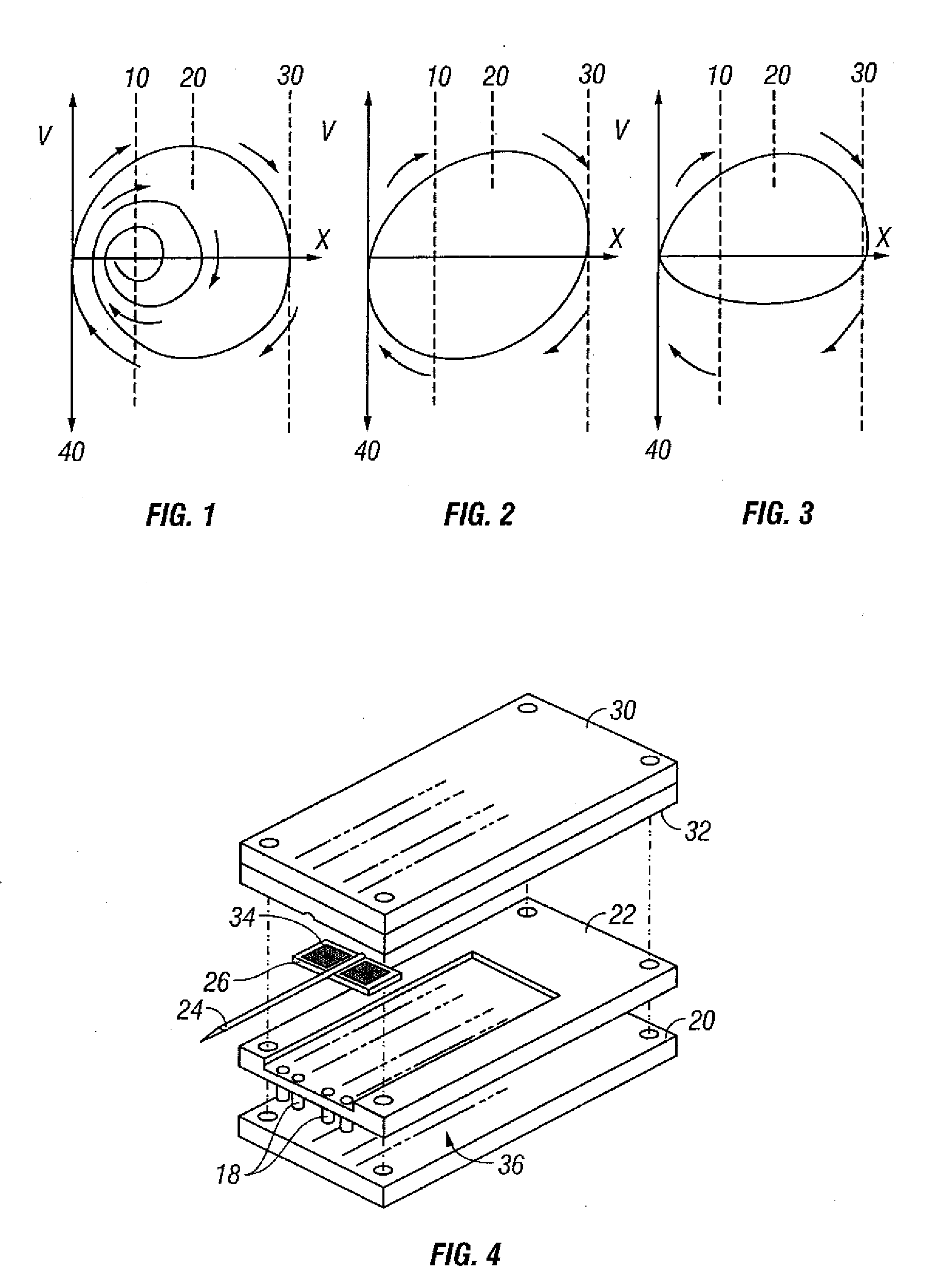
[0221] Variations in skin thickness including the stratum corneum and hydration of the epidermis can yield different results between different users with existing tissue penetration devices, such as lancing devices wherein the tissue penetrating element of the tissue penetration device is a lancet. Many current devices rely on adjustable mechanical stops or damping, to control the lancet's depth of penetration.

[0222] Displacement velocity profiles for both spring driven and cam driven tissue penetration devices are shown in FIG. 1 and 2, respectively. Velocity is plotted against displacement X of the lancet. FIG. 1 represents a displacement / velocity profile typical of spring driven devices. The lancet exit velocity increases until the lancet hits the surface of the skin 10. Because of the tensile characteristics of the skin, it will bend or deform until the lancet tip cuts the surface 20, the lancet will then penetrate the skin until it reaches a full stop 30. At this point displac...


PUM


Abstract

A body fluid sampling system is provided for use on a tissue site. A drive force generator is coupled to penetrating members. The penetrating members are at least partially housed in a penetrating member housing. The penetrating member housing has openings for the penetrating members. The penetrating members are launched along a launch path by the drive force generator through an opening in the penetrating member housing. Analyte sensors are housed in a analyte sensor housing. Each analyte sensor is associated with a penetrating member. The analyte sensor housing and the penetrating member housing are coupled to provide that each analyte sensor is positioned out of a launch path of a penetrating member. The analyte sensor housing includes desiccant pockets for receiving desiccant plugs

Description

RELATED APPLICATIONS [0001] This application claims the benefit of U.S. Ser. No. 60 / 758,774, filed Jan. 12, 2006 This application is also a continuation-in-part of U.S. Ser. No. 11 / 318,334, filed Dec. 22, 2005, which is a divisional of U.S. Ser. No. 10 / 127,395, filed Apr. 19,2002. All of the above-referenced applications are fully incorporated herein by reference.BACKGROUND [0002] 1. Technical Field [0003] The technical field relates to analyte sampling devices, and more specifically, methods and devices for storing analyte sampling and measurement devices in a safe, usable condition. [0004] 2. Description of the Related Art [0005] Lancing devices are known in the medical health-care products industry for piercing the skin to produce blood for analysis. Typically, a drop of blood for this type of analysis is obtained by making a small incision in the fingertip, creating a small wound, which generates a small blood droplet on the surface of the skin. [0006] Early methods of lancing i...

Claims


Application Information

Patent Timeline
Patent Type & Authority Applications(United States)
IPC IPC(8): A61B5/00
CPCA61B5/1411A61B5/1427A61M2005/005A61B5/15186A61B5/15146A61B5/150022A61B5/150061A61B5/150068A61B5/150099A61B5/150152A61B5/150167A61B5/150175A61B5/150221A61B5/150358A61B5/150427A61B5/150503A61B5/150572A61B5/15113A61B5/15117A61B5/15123A61B5/15151A61B5/15153A61B5/15163A61B5/15169A61B5/15171A61B5/15174A61B5/15176A61B5/15184A61B5/157A61B5/15178
Inventor DESHMUKH, AJAYFREEMAN, DOMINIQUEBOECKER, DIRKALDEN, DON
Owner SANOFI AVENTIS DEUT GMBH
Why Eureka
Try Eureka