
Pseudorandom number generator and pseudorandom number generation program

a pseudorandom number and generator technology, applied in the field of pseudorandom number generator and pseudorandom number generation program, can solve the problems of difficult to predict the sequence of pseudorandom numbers to be generated, decrypt or tamper with data,

Inactive Publication Date: 2007-07-26
VICTOR CO OF JAPAN LTD
View PDF5 Cites 23 Cited by
  • Summary
  • Abstract
  • Description
  • Claims
  • Application Information

AI Technical Summary

Benefits of technology

"The present invention provides a pseudorandom number generator and program that can generate a sequence of numbers that is difficult to predict, even if the generated sequence or transmitted / received data is observed. The generator uses a linear feedback shift register and a primitive polynomial to carry out logical operations on a bit string to generate the pseudorandom number sequence. The program includes an initial value generator, a polynomial coefficient generator, a memory to store the generated coefficients, and a selection means to select the appropriate primitive polynomial for the linear feedback shift register. The technical effect of the invention is to provide a secure and efficient method for generating pseudorandom numbers for cryptocommunication purposes."

Problems solved by technology

Even if a third person intercepts the data, the third person has no authentic decryption key, and therefore, is unable to decrypt or tamper with the data.
There is, therefore, a risk that pseudorandom numbers to be generated are guessed from an initial number or from part of a generated pseudorandom number sequence.
If pseudorandom numbers are generated by selecting some of the plurality of linear feedback shift registers, it will be difficult to predict a pseudorandom number sequence to be generated.
Combining linear feedback shift registers having characteristic polynomials of optional coefficients has a problem that it generates a pseudorandom number sequence that is not always an M-sequence (maximum length sequence) and the same pseudorandom number sequence is repeatedly generated at short intervals.
This means that linear feedback shift registers that are not always used must be arranged to deteriorate efficiency.

Method used


Image

  • Pseudorandom number generator and pseudorandom number generation program
  • Pseudorandom number generator and pseudorandom number generation program
  • Pseudorandom number generator and pseudorandom number generation program

Examples


first embodiment

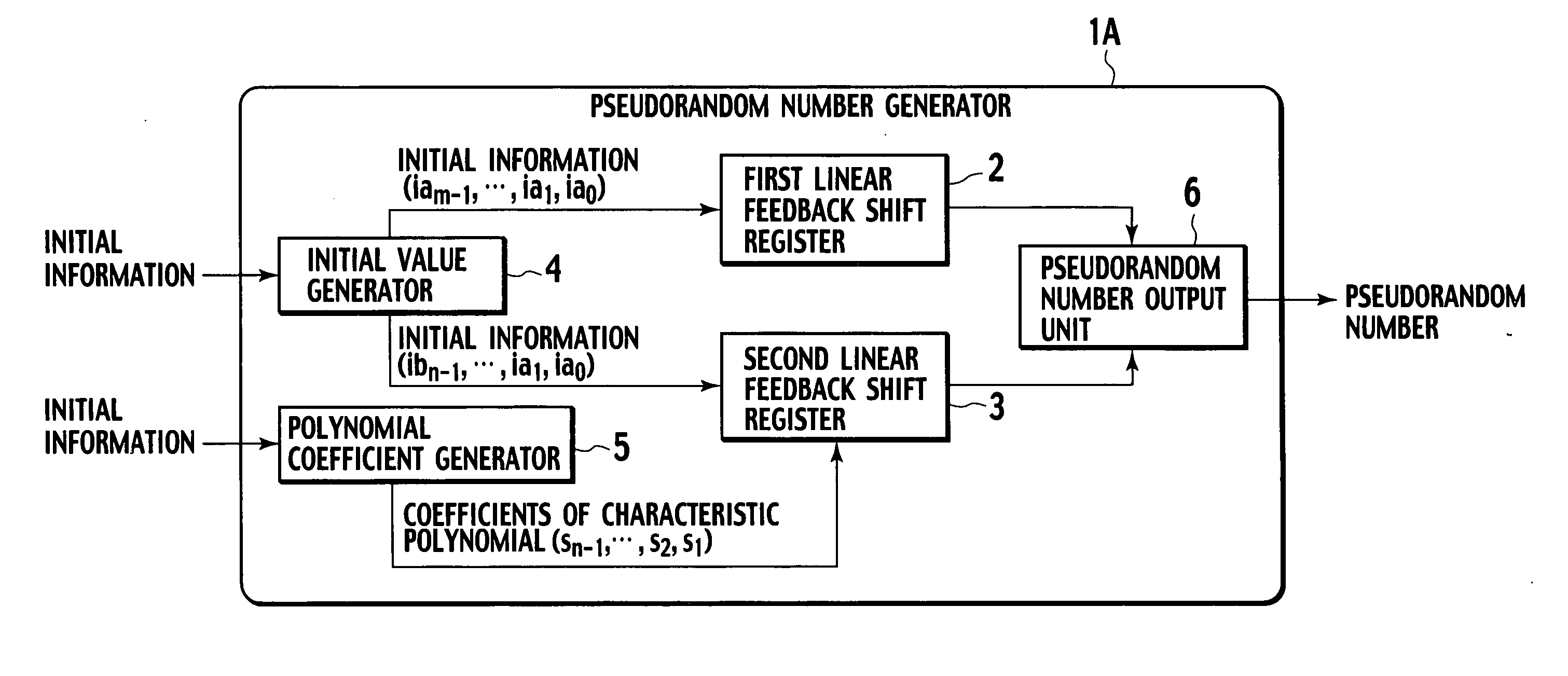
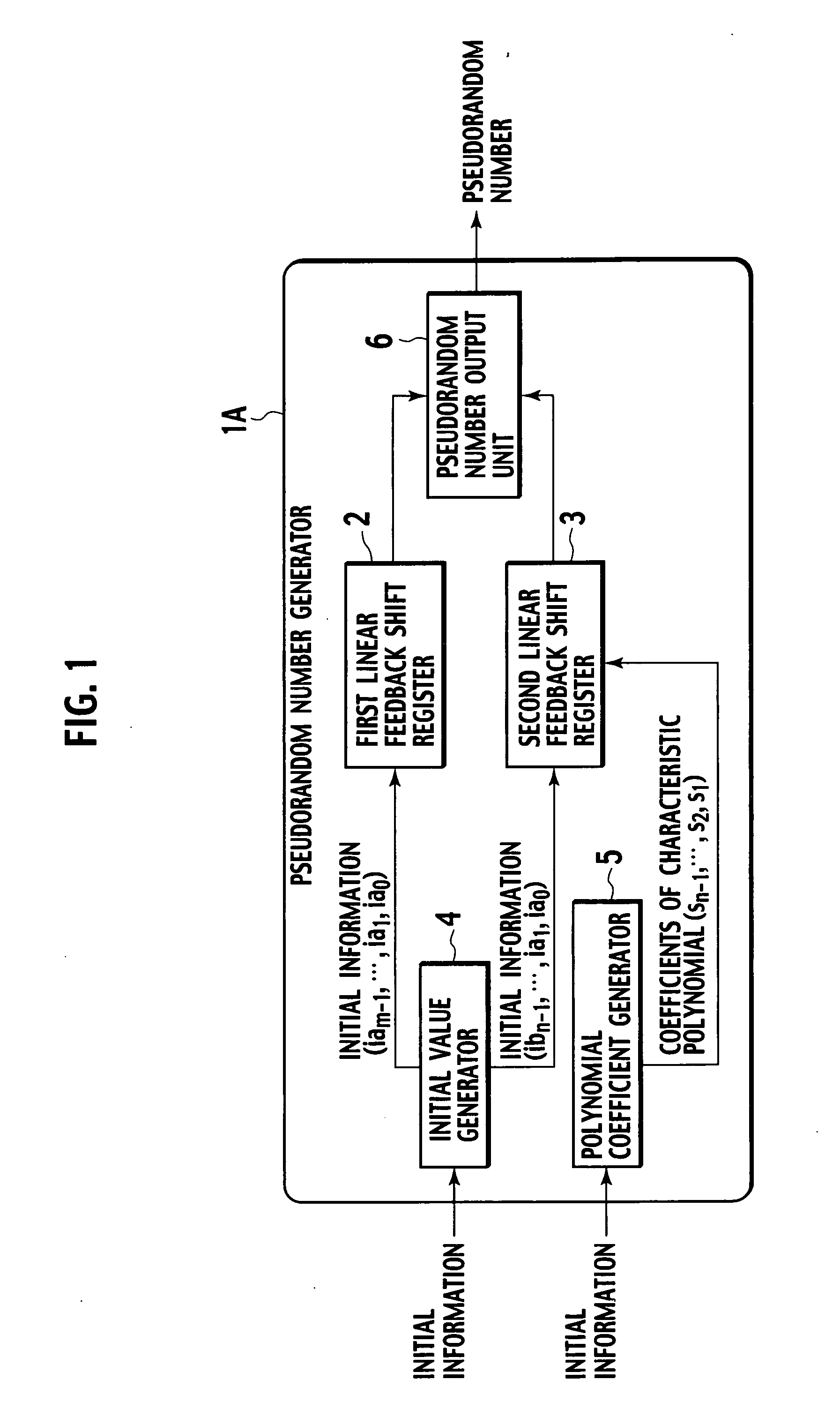
[0022] In FIG. 1, a pseudorandom number generator 1A according to the first embodiment has a first linear feedback shift register 2, a second linear feedback shift register 3, an initial value generator 4, a polynomial coefficient generator 5, and a pseudorandom number output unit 6.

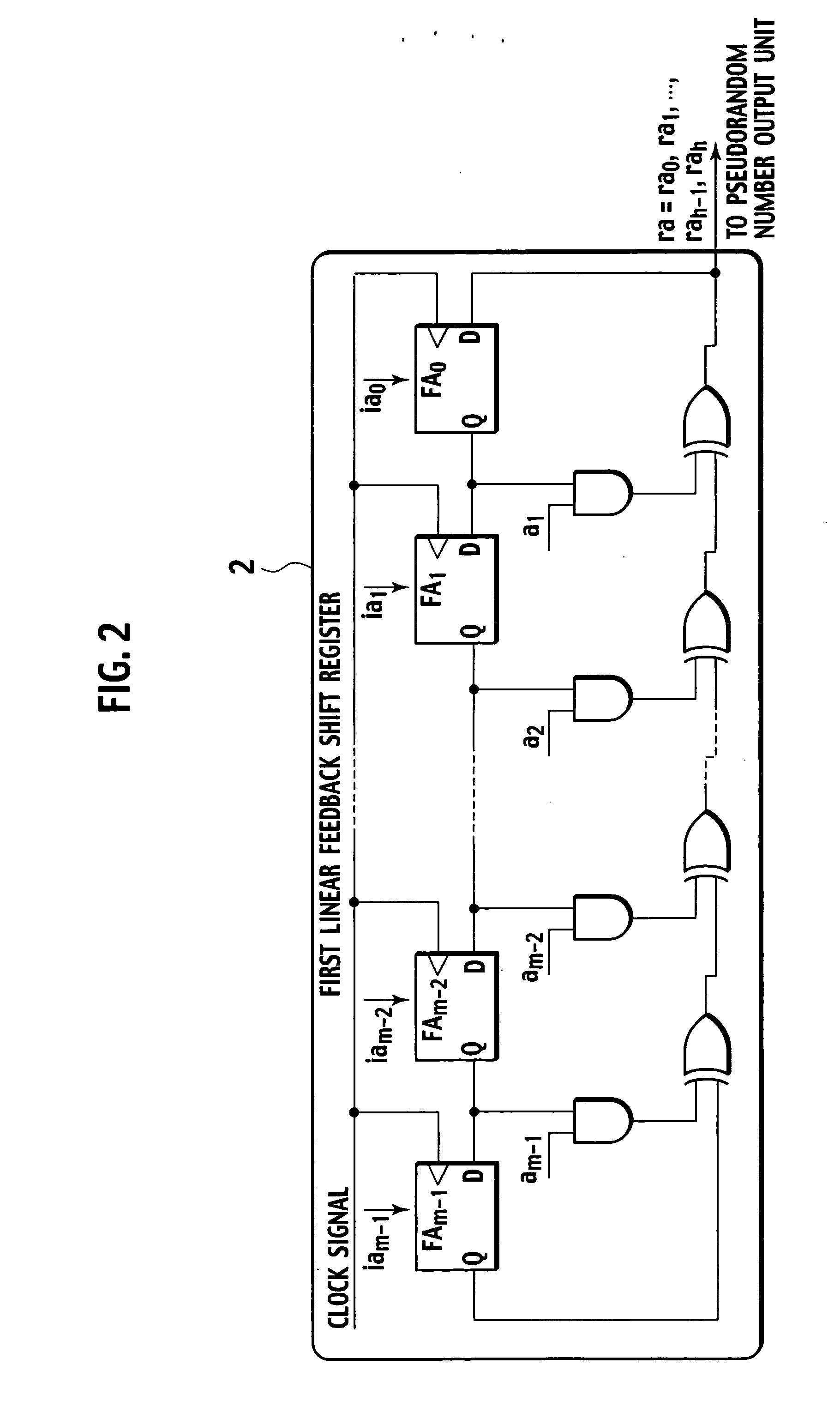
[0023] The first linear feedback shift register 2 is an m-step linear feedback shift register having m flip-flop circuits (to be explained later in detail). The second linear feedback shift register 3 is an n-step linear feedback shift register having n flip-flop circuits (to be explained later in detail).

[0024] The initial value generator 4 has functions of using initial information to be provided externally or using predetermined conditions that may be obtained from always changing information such as date and time information or from physical phenomena such as heat, noise, and the like, generating initial values ia (iam−1, iam−2, . . . , ia1, ia0) accordingly for the flip-flops of the first linear f...

second embodiment

[0044] In FIG. 6, a pseudorandom number generator 1B according to the second embodiment has a first linear feedback shift register 2, a second linear feedback shift register 3, an initial value generator 4, a polynomial coefficient generator 5, a pseudorandom number output unit 6, a primitive polynomial selector 7, and a primitive polynomial memory 8. The same parts as those of the first embodiment are represented with the same numerals and their detailed explanations are omitted.

[0045] The primitive polynomial selector 7 has functions of referring to externally provided initial information, selecting one of primitive polynomials stored in the primitive polynomial memory 8 accordingly, and supplying coefficients a (am−1, . . . , a1) of the primitive polynomial serving as a characteristic polynomial to the first linear feedback shift register 2.

[0046] The primitive polynomial memory 8 stores a plurality of primitive polynomials with identification information, for setting AND circu...

third embodiment

[0053] The third embodiment employs two pseudorandom number generators 1C. For example, one pseudorandom number generator 1 is arranged on a transmission side and the other pseudorandom number generator 1 is arranged on a receive side. The pseudorandom number generators 1C share characteristic polynomial coefficients and initial values (initial data), to generate the same pseudorandom number.

[0054] In FIG. 8, the pseudorandom number generator 1C according to the third embodiment has a first linear feedback shift register 2, a second linear feedback shift register 3, an initial value generator 4, a polynomial coefficient generator 5, a pseudorandom number output unit 6, a primitive polynomial selector 7, a primitive polynomial memory 8, and a communication unit 9. The same parts as those of the first and second embodiments are represented with the same numerals and their detailed explanations are omitted. For the sake of convenience, each component of the pseudorandom number generat...


PUM


Abstract

A pseudorandom number generator (1) has a first linear feedback shift register (2), a second linear feedback shift register (3), an initial value generator (4), a polynomial coefficient generator (5), and a pseudorandom number output unit (6). The initial value generator (4) generates initial values and supplies the same to the first linear feedback shift register (2) and second linear feedback shift register (3). The polynomial coefficient generator (5) generates coefficients of a characteristic polynomial and supplies the same to the second linear feedback shift register (3). The pseudorandom number output unit (6) carries out exclusive-OR operations on bits sequentially provided by the first linear feedback shift register (2) and second linear feedback shift register (3), generates a pseudorandom number sequence, and outputs the same.

Description

TECHNICAL FIELD [0001] The present invention relates to a pseudorandom number generator and pseudorandom number generation program for generating pseudorandom numbers used for cryptocommunication. Background Art [0002] Data communication through telephone, radio, the Internet, and the like is presently carried out by encrypting communication data to protect the data from wiretapping or alteration third persons. A sender of data encrypts the data with an encryption key and transmits the encrypted data. A receiver receives the encrypted data, decrypts the data with a decryption key, and obtains the data. Even if a third person intercepts the data, the third person has no authentic decryption key, and therefore, is unable to decrypt or tamper with the data. [0003] Cryptosystems include a common key cryptosystem and a public key cryptosystem. To best utilize the characteristics of these systems, one of them must be selected according to conditions of use. Any system guarantees the secur...

Claims


Application Information

Patent Timeline
Patent Type & Authority Applications(United States)
IPC IPC(8): G06F7/58
CPCG06F7/584
Inventor INOHA, WATARU
Owner VICTOR CO OF JAPAN LTD
Learn More