Fluid machine for Rankine cycle
a technology of rankine apparatus and flue, which is applied in the direction of liquid degasification, positive displacement liquid engine, separation process, etc., can solve the problems of increasing the connection portions difficult to apply the rankine apparatus to a vehicle, and increasing the structure of the rankine apparatus. , to achieve the effect of safely and surely stopping the expansion device and easy equalizing the pressur
- Summary
- Abstract
- Description
- Claims
- Application Information
AI Technical Summary
Benefits of technology
Problems solved by technology
Method used
Image
Examples
first embodiment
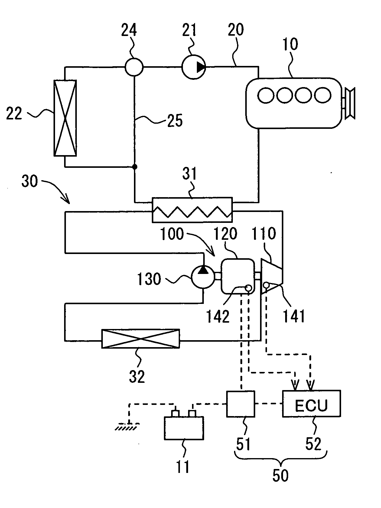
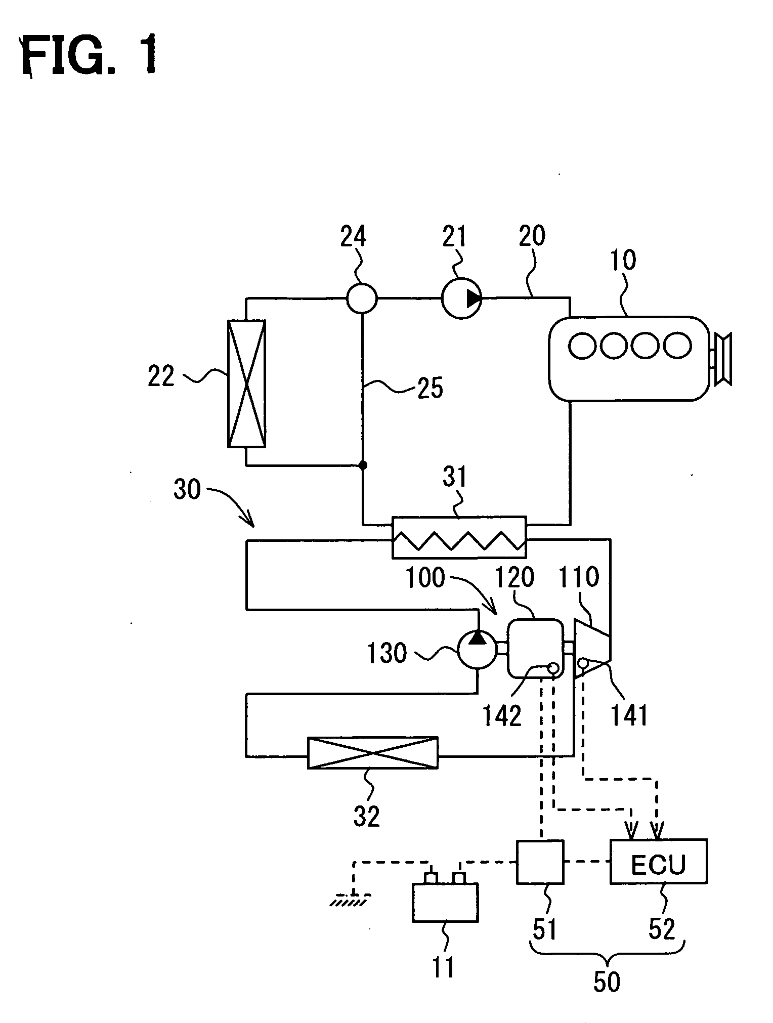
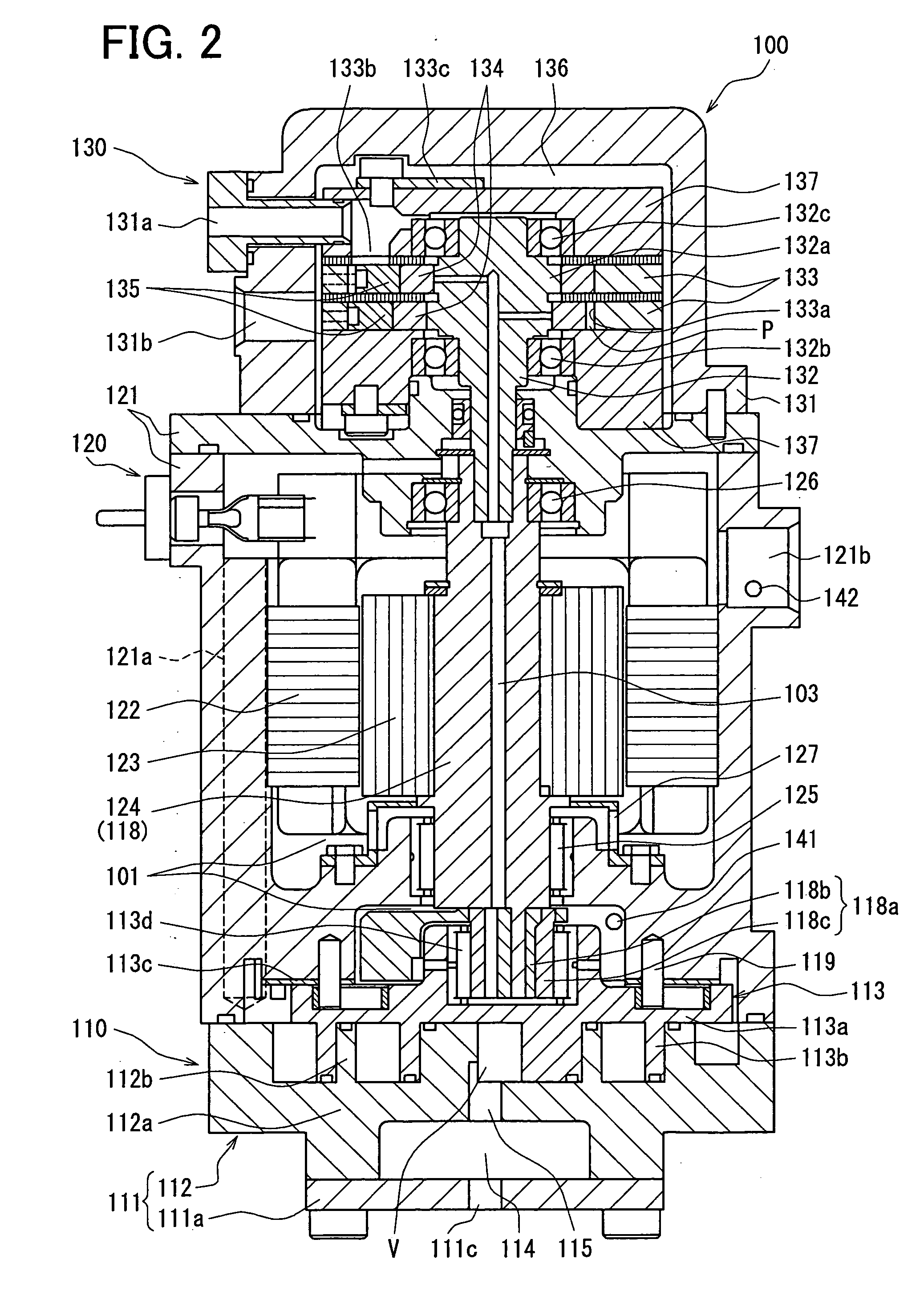
[0062] In a first embodiment, a fluid machine is formed as such a device 100 integrally having a refrigerant pump, an expansion device and an electric power generator (hereinafter also referred to a pump-expansion-generator device). The pump-expansion-generator device 100 is applied to Rankine cycle 30 for a vehicle. The pump-expansion-generator device 100 comprises the expansion device (i.e. an expansion portion of the present invention) 110, a motor generator (i.e. the electric power generator of the present invention) 120 as an electric motor and as the electric power generator, and the refrigerant pump 130, wherein those components are integrally formed. A system structure will be explained hereinafter with reference FIG. 1.
[0063] The Rankine cycle collects energy (as a driving force generated at the expansion device 110) from waste heat generated at an engine 10 (i.e. an external heat energy source of the present invention). The Rankine cycle is formed by the refrigerant pump ...
second embodiment
[0114] A second embodiment of the present invention is shown in FIG. 7. In the second embodiment, a control (a control flow) before starting up the Rankine cycle 30 is different from that for the first embodiment.
[0115] In the control flow of the second embodiment, the steps S130 and S150 of the first embodiment (FIG. 3) are eliminated. Namely, when the controller 52 determines at the step S120 that the viscosity of the lubricating oil is lower than the predetermined viscosity, the controller 52 outputs a command signal at the step S140 for the current supply to the stator 122 so as to heat the refrigerant in the oil pooling portions 101, without calculating the current supply period to the stator 122 of the motor generator 120. The process goes back to the step S100 to detect the temperature and the pressure of the refrigerant by the temperature sensor 141 and the pressure sensor 142. In the case that the viscosity of the lubricating oil becomes higher than the predetermined visco...
third embodiment
[0117] A third embodiment of the present invention is shown in FIG. 8. In the third embodiment, a heating unit for heating the refrigerant in the oil pooling portions 101 is modified, when compared with the first embodiment.
[0118] A water jacket 151 is provided at an outer peripheral portion of the motor housing 121, and a bypass passage 151a is connected to the water jacket 151, wherein the bypass passage 151a bypasses the heating device 31. The water jacket 151 and the bypass passage 151a correspond to a heat medium passage to form the heating unit. An on-off valve 151b is provided at the bypass passage 151a, wherein the on-off valve is controlled by the controller 52 for opening or closing the passage.
[0119] According to the third embodiment, the controller 52 calculates the viscosity of the lubricating oil in the oil pooling portions 101 before the start-up of the Rankine cycle 30 as well as during the normal operation. And the controller 52 opens the on-off valve 151b so that...
PUM
| Property | Measurement | Unit |
|---|---|---|
| Temperature | aaaaa | aaaaa |
| Pressure | aaaaa | aaaaa |
| Power | aaaaa | aaaaa |
Abstract
Description
Claims
Application Information
 - R&D
- Intellectual Property
- Life Sciences
- Materials
- Tech Scout
- Unparalleled Data Quality
- Higher Quality Content
- 60% Fewer Hallucinations
Browse by: Latest US Patents, China's latest patents, Technical Efficacy Thesaurus, Application Domain, Technology Topic, Popular Technical Reports.
© 2025 PatSnap. All rights reserved.Legal|Privacy policy|Modern Slavery Act Transparency Statement|Sitemap|About US| Contact US: help@patsnap.com


